Display panel virtual pixel multiplexing structure, control method and system
A display panel and virtual pixel technology, applied to static indicators, instruments, etc., can solve the problems of single virtual pixel multiplexing and color matching difficulties, and achieve the effects of flexible multiplexing, uniform color matching, and small loss of resolution
- Summary
- Abstract
- Description
- Claims
- Application Information
AI Technical Summary
Problems solved by technology
Method used
Image
Examples
Embodiment approach 1
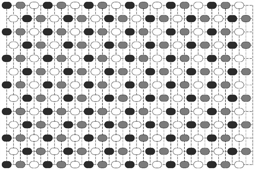
[0040] Embodiment 1, see Figures 1 to 3 This embodiment will be described. In the virtual pixel multiplexing structure of a display panel described in this embodiment, the display panel is composed of a plurality of light-emitting components to form an array structure, and the spacing between two adjacent light-emitting components located in the same row is 1 basic unit. The light-emitting components in adjacent rows and the same column are staggered by half a basic unit, and the light-emitting components adjacent in any direction are light-emitting components with different primary colors;
[0041] Three adjacent light-emitting components of three primary colors form one pixel unit, and there is a case where the same light-emitting component is multiplexed by multiple pixel units.
[0042] The light-emitting component is a single light-emitting body, or a combination of a plurality of light-emitting bodies of the same color.
[0043] The light-emitting body is any one of L...
Embodiment approach 2
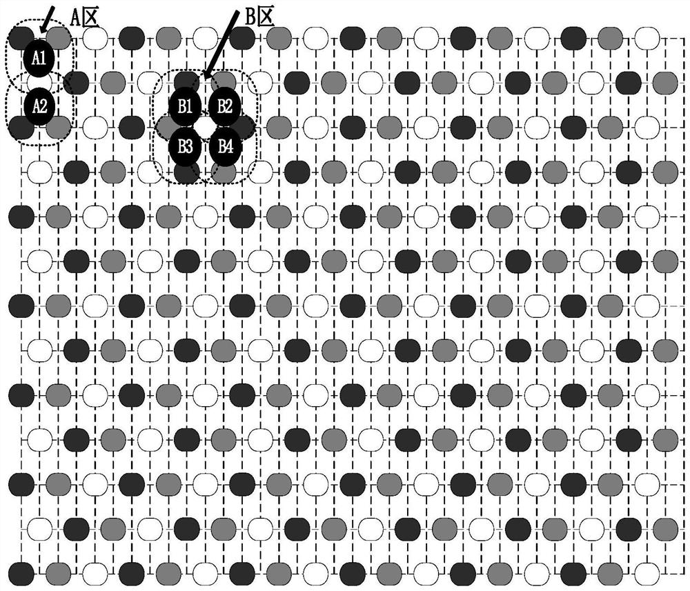
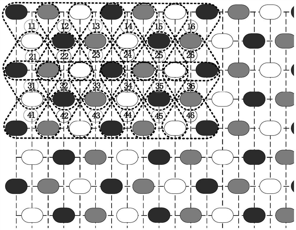
[0046] Embodiment 2, see figure 2 and image 3 Description of this embodiment This embodiment is a further limitation of the dummy pixel multiplexing structure of a display panel described in Embodiment 1. In this embodiment, the three adjacent rows of light-emitting components form two rows of pixel units, each The pixel unit is a triangle composed of three light-emitting components of three primary colors in two adjacent rows, of which one row of pixel units are all equilateral triangles, and the adjacent bottom corners of two adjacent triangles share one light-emitting component, and the other row of pixel units. Both are inverted triangles, and the adjacent bottom corners of two adjacent triangular pixel units share a light-emitting component;
[0047] Each equilateral triangle pixel unit shares one light emitting component with the top corners of the adjacent inverted triangle pixel units in the upper row, and the equilateral triangle pixel unit and the two bottom corne...
Embodiment approach 3
[0053] Embodiment three, see Figure 4 , Figure 5 This embodiment will be described. This embodiment is a further limitation of the virtual pixel multiplexing structure of a display panel described in Embodiment 1. In this embodiment, any adjacent three primary color light-emitting components form a pixel unit, and when the plurality of light-emitting components are composed of In the case of row i and column j, pixel units of row i and column 2j are formed.
[0054] The difference between this embodiment and the second embodiment is that the definition of the pixel unit is different. In this embodiment, any adjacent three-primary color light-emitting components are formed into a pixel unit, forming i rows and 2j columns of pixel units. The pixel cells of , are arranged more closely, see Figure 4 As shown, the pixel units in the same row are alternately arranged in equilateral triangles and inverted triangles, and the pixel units in the same column are also alternately ar...
PUM
 Abstract
Description
Claims
Application Information
 - R&D
- Intellectual Property
- Life Sciences
- Materials
- Tech Scout
- Unparalleled Data Quality
- Higher Quality Content
- 60% Fewer Hallucinations
Browse by: Latest US Patents, China's latest patents, Technical Efficacy Thesaurus, Application Domain, Technology Topic, Popular Technical Reports.
© 2025 PatSnap. All rights reserved.Legal|Privacy policy|Modern Slavery Act Transparency Statement|Sitemap|About US| Contact US: help@patsnap.com


