Interlocking structure of bypass power supply switching device

A power supply switching and interlocking technology, applied in circuit devices, emergency power supply arrangements, circuits, etc., can solve problems such as equipment damage, power supply equipment damage, serious accidents, etc.

Pending Publication Date: 2022-07-29
O SUNG ELECTRIC MACHINERY
View PDF1 Cites 2 Cited by
  • Summary
  • Abstract
  • Description
  • Claims
  • Application Information

AI Technical Summary

Problems solved by technology

[0005] First, in order to maintain, repair and test the automatic transfer switch, after the bypass switch 20 is switched to the normal power supply or the standby power supply, the managers or operators may forget to switch the bypass switch 20, and then connect the joystick to Into the joystick access part 10a to manually switch the power supply of the automatic switching device 10, in this case, it may cause damage to the power supply equipment, and may even cause a fire
That is, the bypass power supply switching device will not break down when the input power of the bypass switch 20 is consistent with the input power of the automatic transfer switch, but when the input power of the bypass switch 20 is different from the input power of the automatic transfer switch In the state, if the operator accidentally switches the power supply of the automatic transfer switch through the joystick access part 10a, it may cause a serious accident
[0006] Second, the problem with the bypass power switching device is that the management personnel use the bypass switch 20 to bypass the power supply, and pull out the automatic transfer switch 10 from the switchboard for testing or maintenance work and then connect it to the original position of the switchboard. , if the input power of the bypass switch 20 is different from the input power of the automatic transfer switch 10, it may cause the aforementioned accident
That is, the manager pulls out the automatic transfer switch 10 from the switchboard 30, and connects the normal power supply or the backup power supply to the automatic transfer switch 10 for testing or maintenance work. In the original position of 30, if the input power of the automatic transfer switch 10 and the bypass switch 20 are inconsistent, it may cause equipment damage, fire and other accidents.

Method used


Image

  • Interlocking structure of bypass power supply switching device
  • Interlocking structure of bypass power supply switching device
  • Interlocking structure of bypass power supply switching device

Examples


Embodiment Construction

[0031] Terms and words used in this specification and claims are not limited to their ordinary or dictionary meanings, and should be construed as defined by the inventors in order to describe the invention in the best possible way, in accordance with the principles that the term concepts can be properly defined meanings and concepts consistent with the technical idea of ​​the present invention.

[0032] Reference below Figure 3 to Figure 9 The interlock structure of the bypass power switching device according to the preferred embodiment of the present invention (hereinafter referred to as the interlock structure) is described.

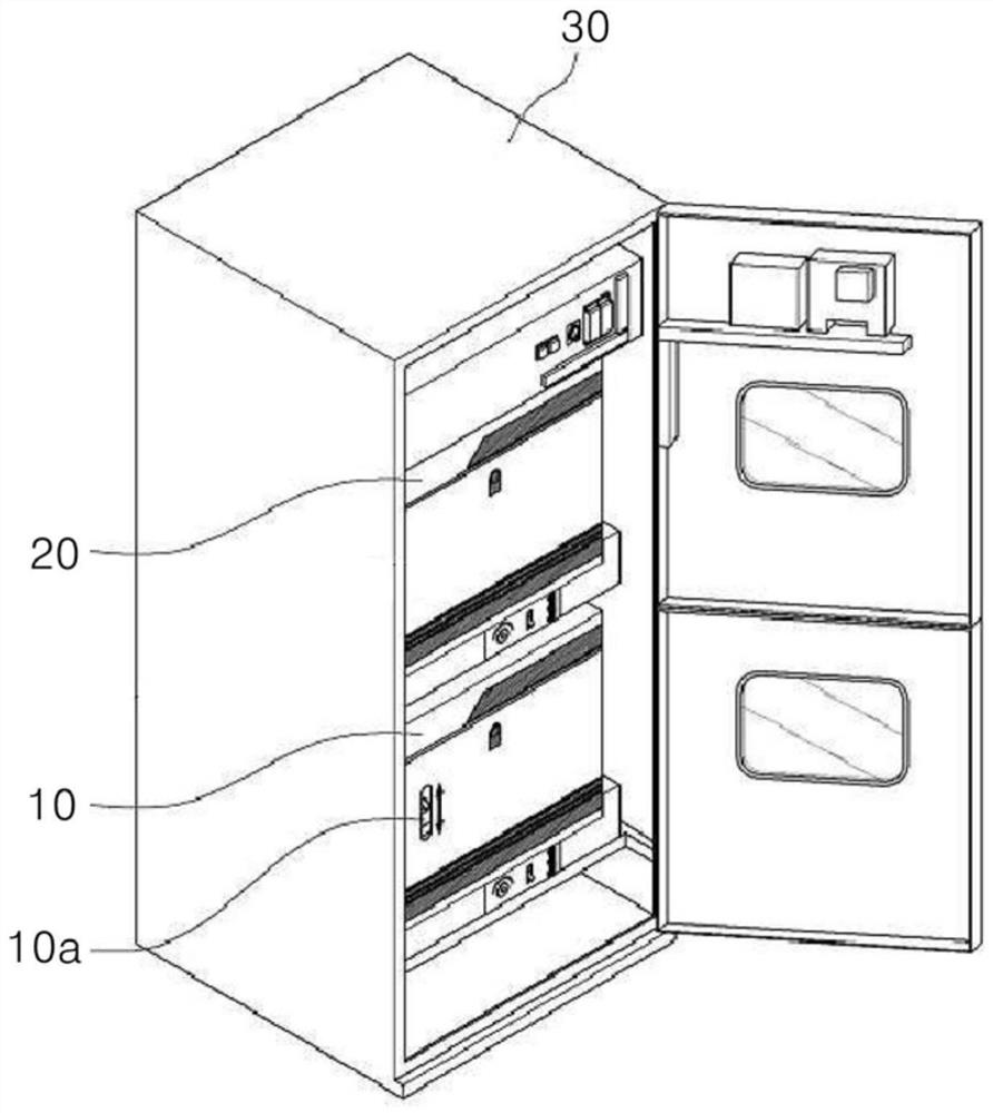
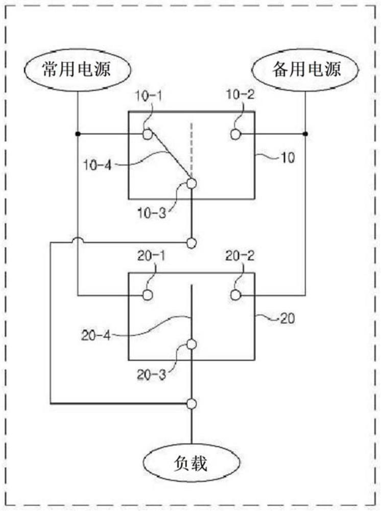
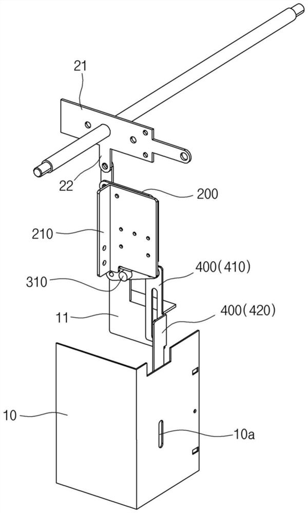
[0033] like image 3 As shown, in the bypass power switching device in which the automatic transfer switch 10 and the bypass switch 20 are connected in parallel, the interlock structure includes an interlock device capable of closing the joystick access portion formed on the automatic transfer switch 10 10a. The bypass switch 20 includes a bypass l...


PUM


Abstract

The present invention relates to an interlocking structure of a bypass power switching device, comprising: an automatic change-over switch having a joystick access part; the bypass switch is in bypass connection with the frequently-used power supply or the standby power supply and comprises a bypass operating lever; and the interlocking device can automatically close the joystick access part. The interlocking device comprises a main connector which is connected to the bypass joystick and always descends towards the lower part of the bypass joystick; the lifting component is linked with the main connector; an elastic connector rotatably attached to a lower portion of the lifting member and having an elastic force capable of rotating upward; and an opening / closing plate which is rotatably connected to the elastic connector, ascends and descends toward the joystick access part on the basis of the rotation action of the elastic connector, and opens and closes the joystick access part. When a supply power source is bypassed through the bypass switch, the joystick access portion is closed regardless of the type of the access power source of the bypass switch to prevent manual switching of the automatic changeover switch, and when the automatic changeover switch is pulled out from the switchboard, the joystick access portion is automatically opened.

Description

technical field [0001] The invention relates to an interlock structure of a bypass power switching device, especially when the bypass power supply is used, the automatic switching switch is physically prevented from being manually switched, and when the automatic switching switch is pulled out from the switchboard, the joystick access part can automatically open. Background technique [0002] Generally speaking, large buildings or factories use the normal power supply (Normal Power Supply) from power plants such as Korea Electric Power Co., Ltd. for use. Only when the normal power supply is abnormal (such as power failure), the internal power generation equipment is used to generate the emergency power supply (Emergency Power Supply). Supply) for use. These large buildings or factories are equipped with automatic power switching devices, which include automatic transfer switches (Automatic Transfer Switch, ATS), which usually connect the common power supply and the load sid...

Claims


Application Information

Patent Timeline
Patent Type & Authority Applications(China)
IPC IPC(8): H01H9/20
CPCH01H9/20H01H9/26H02J9/068H01H2300/018H02B1/14
Inventor 文盛煥黃信午
Owner O SUNG ELECTRIC MACHINERY
Why Eureka
Try Eureka