
Shielding piece fixing structure and connector

A fixed structure and shielding technology, applied in the connection, the parts of the connection device, the protective grounding/shielding device of the connection parts, etc., can solve the problems such as the transmission of the signal performance affecting the shielding effect, and ensure the transmission of the shielding effect and signal performance. , Guaranteed shielding effect, widely used value effect

Pending Publication Date: 2022-07-29
CHINA AVIATION OPTICAL-ELECTRICAL TECH CO LTD
View PDF6 Cites 0 Cited by
  • Summary
  • Abstract
  • Description
  • Claims
  • Application Information

AI Technical Summary

Problems solved by technology

[0002] The terminal is shielded by the shielding sheet on one side. In the mating area, the shielding between the signal terminals is usually achieved by bending the shielding sheet or adding other components. However, since the mating end of the terminal protrudes in a cantilever shape, As a result, when the connector is mated or in a vibrating environment, the mating end of the terminal will swing, so that there is a relative displacement between the signal terminal and the corresponding shielding sheet, which affects the shielding effect and the transmission of signal performance

Method used


Image

  • Shielding piece fixing structure and connector
  • Shielding piece fixing structure and connector
  • Shielding piece fixing structure and connector

Examples


Embodiment Construction

[0056] In order to further illustrate the technical means and effects adopted by the present invention to achieve the predetermined purpose of the invention, the specific embodiments, structures, features and effects of the present invention are described in detail below in conjunction with the accompanying drawings and preferred embodiments.

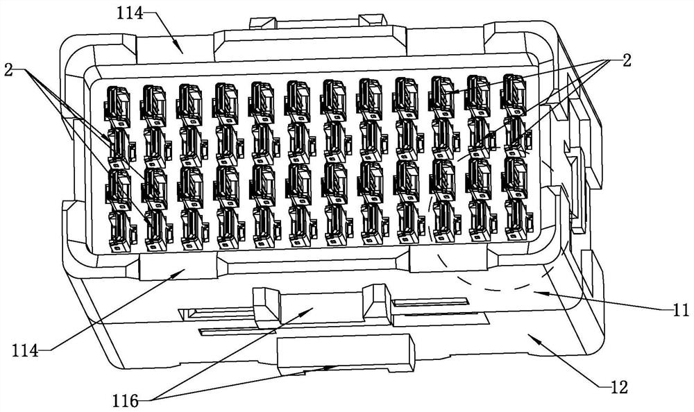
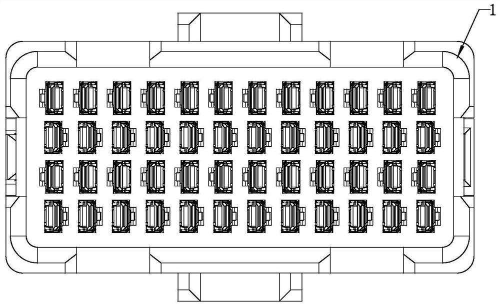
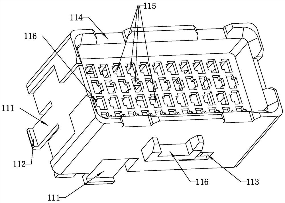
[0057] see Figure 1-16 , which is a schematic structural diagram of each part of the adapter according to the embodiment of the present invention. The adapter includes a housing 1 and a plurality of terminal modules 2 assembled in the housing 1 in a row. Each terminal module 2 includes a terminal 21, an insulator 23 and a The shielding sheet 22, wherein the terminals 21 are located in the insulator 23, the node distance of each terminal 21 is kept constant by the insulator 23, the shielding sheet 22 is covered on one side of the insulator 23, and is used to realize the shielding of the terminals 21 on this side .

[0058] The terminal...


PUM


Abstract

The invention relates to a shielding piece fixing structure and a connector, the shielding piece fixing structure comprises a terminal, an injection molding insert and a shielding sheet, the shielding sheet is provided with a bending part used for accommodating a differential signal pair insertion end and realizing shielding between adjacent differential signal pairs, the bends are distributed at intervals by skipping one differential signal pair in the arrangement direction of the differential signal pair; the plastic wrapping the insertion end of the differential signal pair forms a terminal fixing part, and the terminal fixing part is positioned in the adaptive bend through a buckle structure so as to prevent relative displacement between the differential signal pair and the shielding sheet. According to the invention, the plastic wraps the plugging end, so that the stability of the plugging end of the signal pair is enhanced, the bending of the shielding sheet realizes the comprehensive shielding between the signal pair, the shielding effect between the signal pair is ensured, and the connection and fixation between the plastic and the bending ensure the constant distance between the plugging end terminal and the shielding sheet. And the shielding effect and the transmission of signal performance are ensured.

Description

technical field [0001] The invention belongs to the technical field of connectors, and in particular relates to a shield fixing structure and a connector. Background technique [0002] The terminals are shielded by the shielding sheet on one side. In the insertion area, the shielding between the signal terminals is often achieved by bending the shielding sheet or adding other components. However, since the insertion end of the terminal is cantilevered, As a result, when the connector is mated or in a vibration environment, the mating end of the terminal will swing, thereby causing a relative displacement between the signal terminal and the corresponding shielding sheet, thereby affecting the shielding effect and the transmission of signal performance. SUMMARY OF THE INVENTION [0003] In order to solve the above problems, the present invention provides a shielding member fixing structure, which can fix the insertion end by plastic wrapping the area outside the contact surf...

Claims


Application Information

Patent Timeline
Patent Type & Authority Applications(China)
IPC IPC(8): H01R13/648H01R13/646H01R13/405H01R13/02H01R13/502
CPCH01R13/648H01R13/646H01R13/405H01R13/02H01R13/502
Inventor 李俊范帅周国奇袁俊峰鲁中原王兴理想王冲
Owner CHINA AVIATION OPTICAL-ELECTRICAL TECH CO LTD
Learn More