
Device and method for light-assisted distance determination, control unit and working device

A light-assisted, distance-based technology that can be used in vehicles or robotics to solve problems such as high overhead

Pending Publication Date: 2022-07-29
ROBERT BOSCH GMBH
View PDF0 Cites 0 Cited by
  • Summary
  • Abstract
  • Description
  • Claims
  • Application Information

AI Technical Summary

Problems solved by technology

Such systems are generally time-of-flight measurements of light-assisted pulses and therefore require a relatively high outlay in terms of measurement technology, especially with regard to detectors and analytical processing mechanisms

Method used


Image

  • Device and method for light-assisted distance determination, control unit and working device
  • Device and method for light-assisted distance determination, control unit and working device
  • Device and method for light-assisted distance determination, control unit and working device

Examples


Embodiment approach

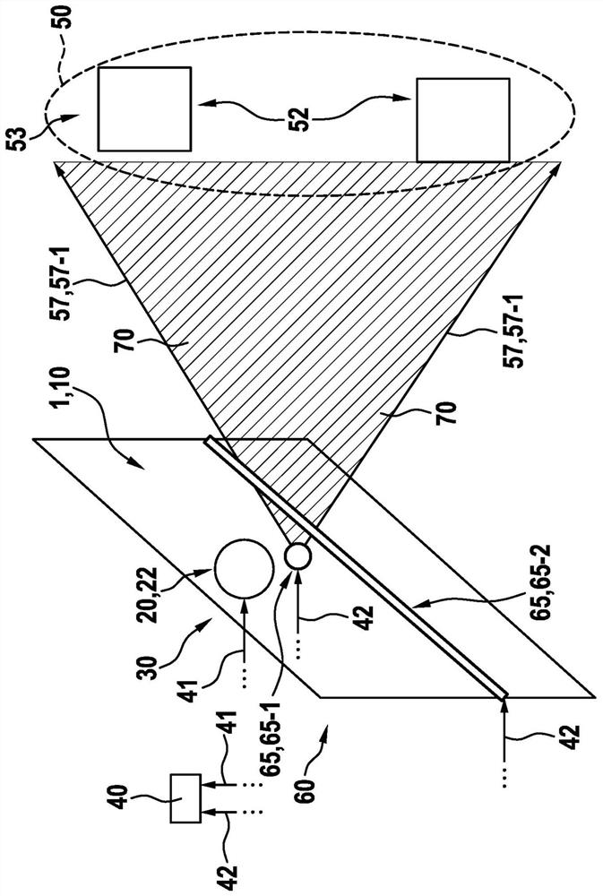
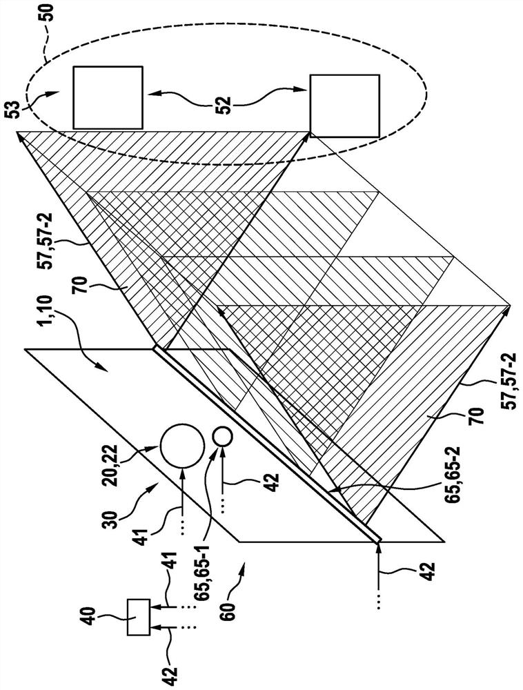
[0084] Alternatively, the order of illumination using the first and second light sources 65-1 and 65-2 may be swapped (and then accounted for computationally accordingly).

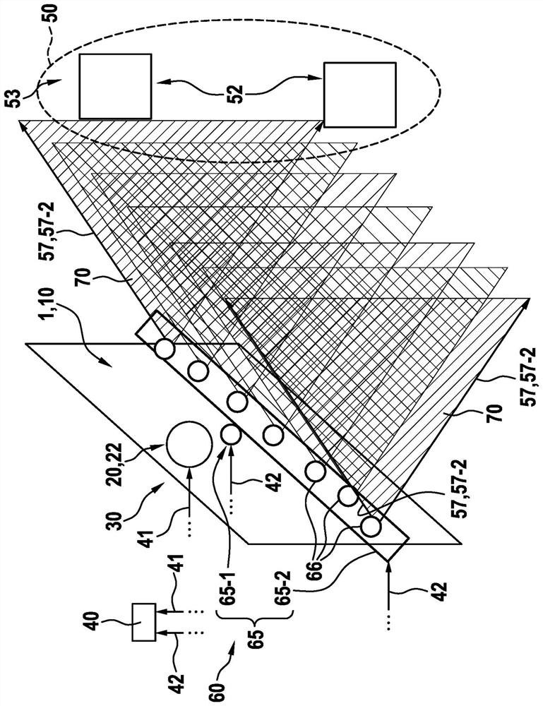
[0085] Figures 3 to 8 A more specific application case of the concept according to the invention for light-assisted distance determination of an object 52 in the field of view 50 is shown schematically in a side view.

[0086] according to image 3 The present invention can also be used instead of using as in figure 1 and figure 2 The uniform rod-shaped light source 65-2 as shown in is instead implemented using a distributed light source 66, which can also be understood as a partial light source.

[0087] Thus, the light of rod source 65-2 is combined from the light of a single source or partial light source 66.

[0088] But here, then the resulting power dependence on the pixel may have the same figure 1 and figure 2 The ideal case of illumination by the cylindrical light source 65-2 is slightly di...


PUM


Abstract

The invention relates to a method for the light-assisted distance determination of an object (52) in a field of view (50), in which: (i) the field of view (50) is illuminated successively with two light sources (65-1, 65-2) with primary light (57) of the light sources (65-1, 65-2), which differ with respect to the respective, in particular predefined, intensity distance laws, (ii) for each illumination, the primary light (57) of the light sources (65-1, 65-2) differs from the intensity distance laws (57) of the light sources (65-1, 65-2), and (ii) for each illumination, the primary light (57) of the light sources (65-1, 65-2) of the light sources (65-1, 65-2) of the field of view (50). The intensity of the secondary light (58) reflected by the object (52) from the field of view (50) is quantitatively detected by determining intensity values characterizing the corresponding intensity, (iii) the determined intensity values are correlated to each other, in particular taking into account the respective intensity distance laws, and (iv) ascertaining and / or providing a value representative of the distance (R) of the object (52) from the formation relationship.

Description

technical field [0001] The invention relates to a device and a method for light-assisted distance determination of objects in the field of view, a corresponding control unit and a work device configured in such a manner, wherein the work device can be designed in particular as a vehicle or robot. Background technique [0002] So-called LiDAR systems (LiDAR - LiDAR: Light Detection and Ranging), designed to impinge the field of view with light or infrared radiation, and capture and analyze the radiation reflected back from the field of view to analyze the field of view and detect Among them, objects are increasingly being used to probe the environment of work equipment, especially vehicles. Such systems are generally time-of-flight measurements of light-assisted pulses and therefore require relatively high overhead in terms of measurement technology, especially in terms of detectors and analytical processing mechanisms. SUMMARY OF THE INVENTION [0003] In contrast, the m...

Claims


Application Information

Patent Timeline
IPC IPC(8): G01S17/08
CPCG01S17/08G01S7/4815G01C3/02
Inventor M·哈塔斯
Owner ROBERT BOSCH GMBH
Learn More