
Die cavity structure, die design method, blowing method and blowing control system

A design method and control system technology, applied in household appliances, other household appliances, hollow objects, etc., can solve problems such as inconsistent radial displacement, difficulty in realization or control, and uneven wall thickness, so as to slow down the plastic ductility and increase Partial wall thickness, the effect of uniform wall thickness

Pending Publication Date: 2022-08-02
GUANG DONG XING LIAN PRECISE MACHINERY
View PDF1 Cites 0 Cited by
  • Summary
  • Abstract
  • Description
  • Claims
  • Application Information

AI Technical Summary

Problems solved by technology

[0004] However, for containers with irregular shapes (such as containers with rectangular, oval, and oblong radial cross-sections), the radial displacement along the circumference is inconsistent. Taking a container with a rectangular radial cross-section as an example, the radial displacement of the container There are long sides and short sides in the cross-section. When the container is formed, the radial displacement of the long side and the short side along the circumference is inconsistent. During the radial displacement process of container blowing, the part of the container blank that forms the short side first contacts the cavity, and the container blank is formed. The part of the short side is cooled first, so that the plastic of this part becomes thicker due to the decrease of ductility; the plastic of the part forming the long side of the container blank maintains good ductility and continues to stretch, and has a thinner thickness than the short side, resulting in The container formed by blowing has the problem of uneven wall thickness
[0005] In addition, for a specific container (such as a container with a handle), it is necessary to increase the local wall thickness of the container when blowing, which is difficult to achieve or control with traditional blowing molds and blowing methods

Method used


Image

  • Die cavity structure, die design method, blowing method and blowing control system
  • Die cavity structure, die design method, blowing method and blowing control system
  • Die cavity structure, die design method, blowing method and blowing control system

Examples


Embodiment

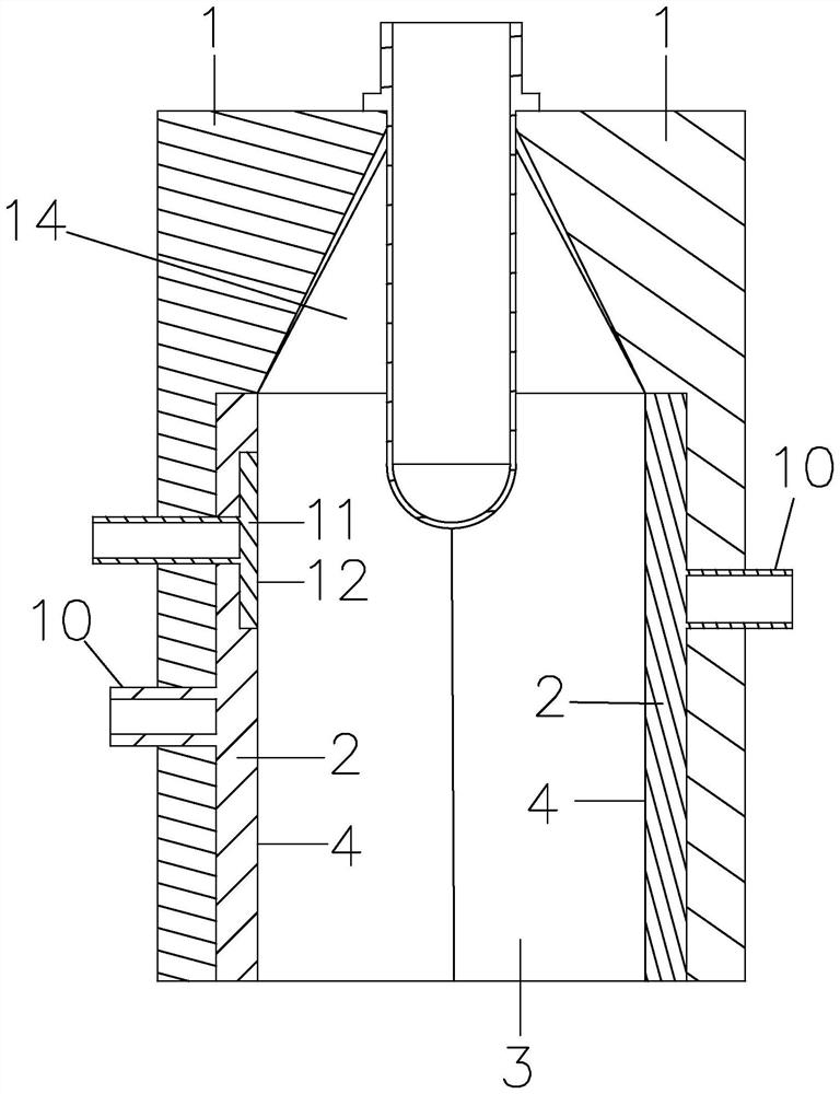
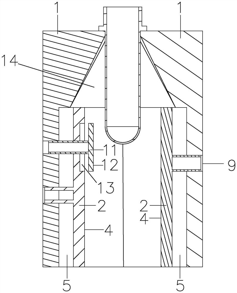
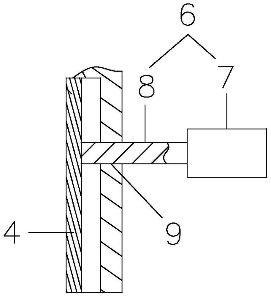
[0053] like Figure 1 to Figure 19 As shown, the present embodiment discloses a cavity structure comprising a cavity half-mold 1 and at least one first insert 2 combined to form the cavity body, the cavity half-mold 1 having a first part defining the shape of the main body of the container at least A molding surface 3, the first insert 2 has at least a part of the main body shape defining the container A second molding surface 4, the first insert 2 has at least a first position initially protruding into the cavity body and a retracted The second molding surface 4 defines a second position of the shape of the part of the main body; wherein the first position of the first insert 2 cannot affect the placement of the preform into the mold cavity, and the distance between the first position and the central axis of the mouth of the preform should be greater than that of the container The radius of the blank.

[0054] As a further improvement of the present invention, the mold cavity ...

Embodiment approach

[0058] Mode 1, both ends of the spring 19 are directly connected to the back of the first insert 2 and the bottom of the first accommodating groove 5 respectively.

[0059] Method 2: The bottom of the first accommodating groove 5 is provided with a first blind connection hole 20 for the end of the spring 19 to be embedded and fixed. The diameter of the first blind connection hole 20 is the same as the outer diameter of the corresponding end of the spring 19 Adaptation; the back of the first insert 2 is provided with a second blind connection hole 21 for the end of the spring 19 to be embedded and fixed, and the aperture of the second blind connection hole 21 is compatible with the outer diameter of the corresponding end of the spring 19 Matching; thus facilitating the connection of the spring 19.

[0060] Mode 3: A guide structure is added. The bottom of the first accommodating groove 5 is provided with a guide hole 22 along the telescopic direction of the first insert 2, and ...


PUM


Abstract

The invention discloses a mold cavity structure, a mold design method, a blowing method and a blowing control system, and belongs to the technical field of blowing forming, the mold cavity structure comprises a mold cavity half mold and at least one first insert which are combined to form a mold cavity main body, and the mold cavity half mold is provided with a first forming surface for at least limiting part of the main body shape of a container; the first insert is provided with a second forming surface for at least limiting part of the main body shape of the container, the first insert is at least provided with a first position for initially stretching into the mold cavity main body and a second position for limiting part of the main body shape by the second forming surface after the first insert retracts, and the first insert can be suitable for blowing forming of the container with an irregular shape; and the device is also suitable for blowing forming of specific containers.

Description

technical field [0001] The invention belongs to the technical field of blow molding, and specifically relates to a mold cavity structure, a mold design method, a blow molding method and a blow molding control system. Background technique [0002] In the prior art, the container is formed by blowing the container blank in the blowing mold. During the blowing process, the heated container blank is stretched and then is axially displaced and radially displaced and then attached to the bottle. Cavities to form containers. [0003] Containers with regular shapes (such as containers with a square or cylindrical radial cross-section) are formed by uniform radial displacement along the circumferential direction, and the wall thickness of the container formed by blowing is uniform. [0004] However, for a container with an irregular shape (such as a container with a rectangular, oval, oval, etc. radial cross-section), the radial displacement along the circumferential direction is in...

Claims


Application Information

Patent Timeline
Patent Type & Authority Applications(China)
IPC IPC(8): B29C49/48B29C49/78B29L22/00
CPCB29C49/4815B29C49/78B29L2022/00B29L2031/7158
Inventor 谢国基姜晓平林昌武胡志国方英卢佳杨建茁
Owner GUANG DONG XING LIAN PRECISE MACHINERY
Learn More