Novel municipal engineering safety protection device
A safety protection device and a new municipal technology, applied in the field of new municipal engineering safety protection devices, can solve the problems of low support efficiency, prone to collapse, different thicknesses, etc., and achieve the effect of improving support efficiency and convenient use.
- Summary
- Abstract
- Description
- Claims
- Application Information
AI Technical Summary
Problems solved by technology
Method used
Image
Examples
Embodiment 1
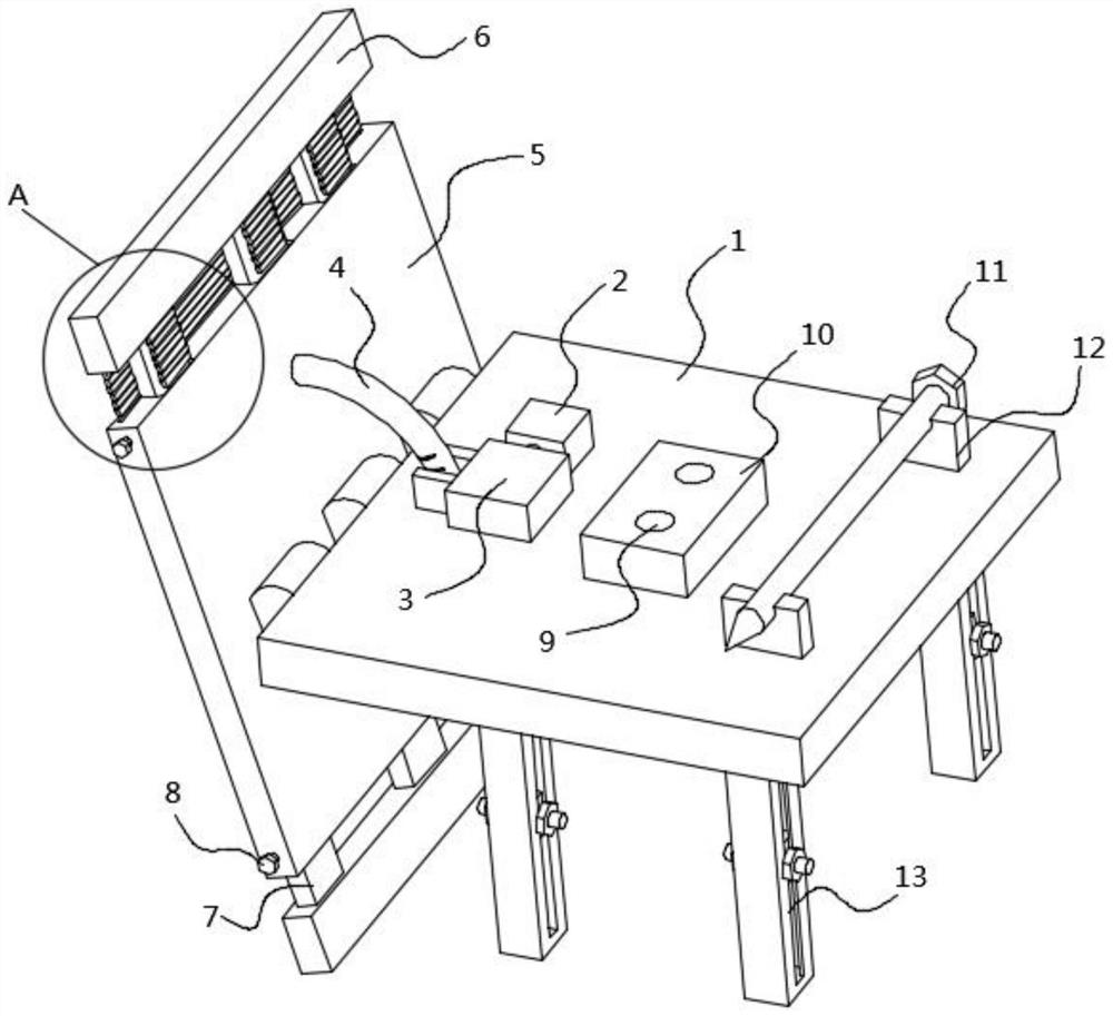
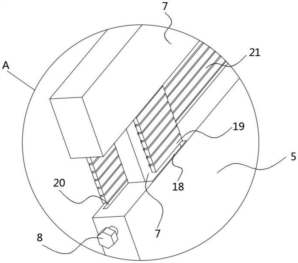
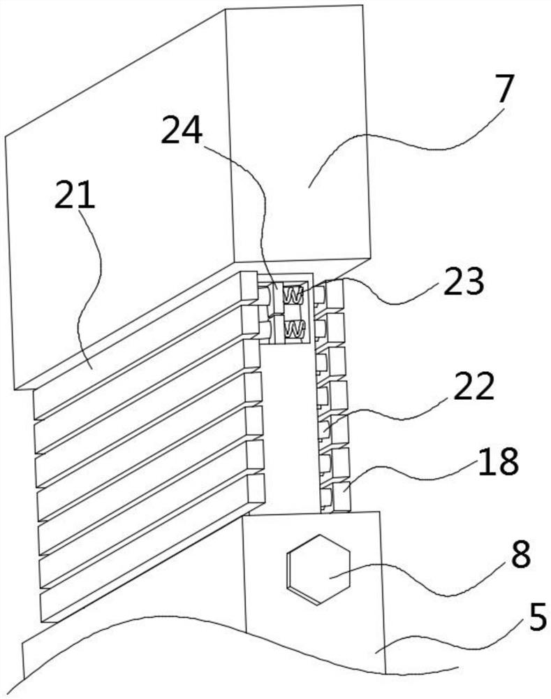
[0023] refer to Figure 1-5 , a new type of municipal engineering safety protection device, including a main board 1, a support plate 5, an arc rod 4 and a clamping mechanism, the middle part of the support plate 5 is hinged with one side of the main board 1, and the arc rod 4 is used to support the railway under the roadbed or It is the roadbed of the expressway, the arc rod 4 is installed on one side of the support plate 5 and penetrates the main board 1, the clamping mechanism is installed on the upper end of the main board 1 and close to the arc rod 4, the clamping mechanism can clamp the arc rod 4, and also includes The outer expansion plate 6, the pressing bolt 8, the slot 18 and the insertion plate 7, the insertion plate 7 is installed on one side of the outer expansion plate 6, the slot 18 is opened on both sides of the support plate 5, and the insertion plate 7 on the side of the outer expansion plate 6 is inserted Inside the slot 18, the plug-in board 7 can be retrac...
Embodiment 2
[0026] refer to Figure 1-5 , as another preferred embodiment of the present invention, the difference from Embodiment 1 is that the clamping mechanism includes a driving motor 2, a clamping block 3, a fixed clamping plate 14, a movable clamping plate 15 and a driving threaded rod 17, and the driving motor 2 and the clamp The clamping block 3 is installed on the upper end of the main board 1, the driving threaded rod 17 is installed on the output shaft of the driving motor 2, the fixed clamping plate 14 is installed on the side of the clamping block 3, the hollow side of the clamping block 3 is opened, and the movable clamping plate 15 is inserted into the clamping block Inside 3, the driving threaded rod 17 is inserted into the clamping block 3 and penetrates the movable splint 15, the fixed splint 14 and the movable splint 15 are located on both sides of the arc rod 4, the driving motor 2 is activated, and the driving motor 2 drives the driving threaded rod 17 to rotate, driv...
Embodiment 3
[0028] refer to Figure 1-5 , as another preferred embodiment of the present invention, the difference from Embodiment 2 is that it also includes a support leg 13, a side groove 25, a weight 26, a compression nut 27 and a threaded rod 28. The interior of the support leg 13 is hollow and installed on the At the lower end of the main board 1, side grooves 25 are opened on both sides of the support leg 13, the weight block 26 is placed inside the support leg 13, the threaded rod 28 is installed on both sides of the weight block 26 and passes through the side groove 25, and the compression nut 27 is sleeved on the thread On the rod 28 and press the side of the support leg 13, by adjusting the height of the weight 26, then rotate the compression nut 27 to press the side of the support leg 13, so that the weight 26 is fixed inside the support leg 13, thereby changing the center of gravity of the support leg 13. position, improve the stability of the overall device, and adapt to the ...
PUM
 Abstract
Description
Claims
Application Information
 - R&D Engineer
- R&D Manager
- IP Professional
- Industry Leading Data Capabilities
- Powerful AI technology
- Patent DNA Extraction
Browse by: Latest US Patents, China's latest patents, Technical Efficacy Thesaurus, Application Domain, Technology Topic, Popular Technical Reports.
© 2024 PatSnap. All rights reserved.Legal|Privacy policy|Modern Slavery Act Transparency Statement|Sitemap|About US| Contact US: help@patsnap.com


