Gas-liquid two-phase flow pattern identification and characterization method, detection device and application

A gas-liquid two-phase flow and flow pattern identification technology, which is applied in the field of gas-liquid two-phase flow pattern identification and two-phase interface shape characterization, can solve the problems of laminar flow distinction, unresearched flow pattern interface shape, etc., and achieves wide application Foreground effect

Pending Publication Date: 2022-08-02
CHINA PETROLEUM & CHEM CORP +1
View PDF2 Cites 0 Cited by
  • Summary
  • Abstract
  • Description
  • Claims
  • Application Information

AI Technical Summary

Problems solved by technology
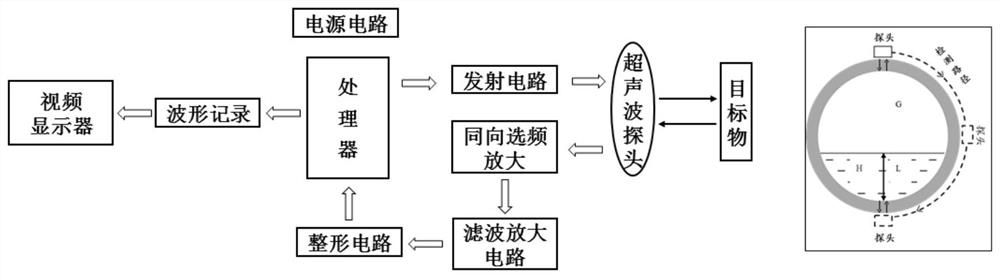
[0010] To sum up, the prior art does not distinguish laminar flow with different interface shapes, and at the same time, the interface shape of flow patterns other than flat laminar flow has not been studied

Method used


Image

  • Gas-liquid two-phase flow pattern identification and characterization method, detection device and application
  • Gas-liquid two-phase flow pattern identification and characterization method, detection device and application
  • Gas-liquid two-phase flow pattern identification and characterization method, detection device and application

Examples


Embodiment 1

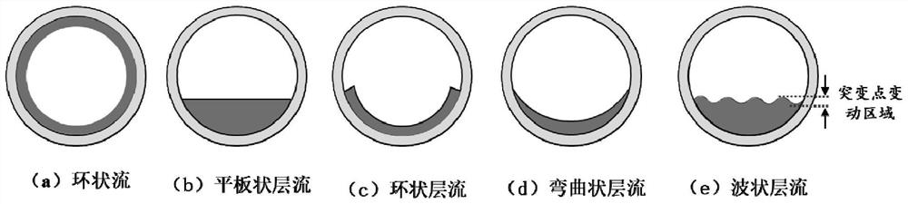
[0091] Annular laminar flow, identification method: there is no sudden change point, the entire detection area is a solid-liquid interface, the thickness of the liquid film at each position is not 0, and the echo curve does not change with time;

[0092]Interface characterization: Determine the thickness of the liquid film at 0 o'clock, 3 o'clock, and 6 o'clock respectively, and then connect the three points to determine the shape of the right half of the interface. The interface shape is as attached. figure 2 (a);

Embodiment 2

[0094] Flat laminar flow, identification method: there is a sudden change point, the thickness of the liquid film at the sudden change point is 0, at the same time, the height of the sudden change point position is equal to the liquid film thickness at 6 o'clock, and the echo curve is stable;

[0095] Interface characterization: Determine the sudden change point and the thickness of the liquid film at 6 o'clock respectively, and then connect the two points to determine the shape of the interface in the right half. attached figure 2 (b).

Embodiment 3

[0097] Annular laminar flow, identification method: there is a sudden change point, the thickness of the liquid film at the sudden change point is not 0, and the thickness of the liquid film at the sudden change point is equal to the thickness of the liquid film at the 6 o'clock position, and the echo curve is stable;

[0098] Interface characterization: Determine the thickness of the liquid film at 0 o'clock, 3 o'clock, and 6 o'clock, respectively, and then connect the three points to determine the shape of the interface in the right half, and the left half is symmetrical according to the connection line between 0 o'clock and 6 o'clock The principle is complete, and the interface shape is as attached figure 2 (c).


PUM


Abstract

The invention discloses a gas-liquid two-phase flow pattern recognition and characterization method, a detection device and application, and relates to the technical field of multiphase flow measurement and flow pattern recognition. An ultrasonic detection device is adopted to detect a pipeline, echo signals are collected, and discrimination parameters are obtained; then, flow pattern recognition is carried out in combination with the discrimination parameters, and the types of flow pattern recognition are slug flow, annular flow and laminar flow; performing interface shape printing according to a result obtained by the flow pattern recognition, and finally outputting a result after the flow pattern recognition and the interface shape printing. According to the method, besides slug flow, annular flow and flat laminar flow, laminar flow patterns of other three different interface shapes can be recognized, meanwhile, two-phase interface shapes of different flow patterns are accurately described, and the problems that in the prior art, flow pattern recognition is not comprehensive, interface shape description is not comprehensive, and accuracy is low are solved. The method makes up the blank in the field of laminar flow pattern recognition and interface shape description of different interface shapes, and has a wide application prospect.

Description

technical field [0001] The invention relates to the field of multiphase flow measurement technology and flow pattern identification technology, in particular to a gas-liquid two-phase flow flow pattern identification and two-phase interface shape characterization method and device, which are suitable for two-phase flow pattern identification and accumulation in oil and gas transmission pipelines. Judgment of fluid condition. Background technique [0002] The identification of gas-liquid two-phase flow pattern has always been a hotspot in the field of oil and gas transmission pipeline research. Accurate identification of two-phase flow pattern not only helps to accurately characterize the flow characteristics and heat and mass transfer characteristics of the fluid, but also helps It is used to predict the flow state of the undetected area of ​​the pipeline, so as to achieve the purpose of reasonably setting the transportation parameters, effectively formulating the pigging sy...

Claims


Application Information

Patent Timeline
Patent Type & Authority Applications(China)
IPC IPC(8): G01N29/024G01M10/00G01B17/02
CPCG01N29/024G01M10/00G01B17/02
Inventor 花靖蒋秀于超靳彦欣夏晞冉刘铭刚高凯歌
Owner CHINA PETROLEUM & CHEM CORP
Why Eureka
Try Eureka