Eureka AIR delivers breakthrough ideas for toughest innovation challenges, trusted by R&D personnel around the world.

Compact transmission structure of adjacent joints and mechanical arm

A transmission structure, compact technology, applied in the direction of manipulators, program control manipulators, joints, etc., can solve the problems of unfavorable miniaturization and light weight of robots, inability to obtain power output, and inability to obtain robots, and achieve compact structure, reliability and safety. , the effect of strong power output

Pending Publication Date: 2022-08-05
SICHUAN FUDE ROBOT
View PDF0 Cites 0 Cited by
  • Summary
  • Abstract
  • Description
  • Claims
  • Application Information

AI Technical Summary

Problems solved by technology

[0002] In the prior art, since the components in the integrated joint are composed of coaxial series, the length of the entire joint is relatively long, resulting in a relatively large mechanical arm, which is not conducive to the miniaturization and weight reduction of the robot.
The motor is always installed between the harmonic reducer and the holding brake. Without increasing the overall size of the joint, the size of the motor is limited and cannot obtain greater power output, resulting in the robot being unable to obtain a greater load-to-weight ratio.

Method used


Image

  • Compact transmission structure of adjacent joints and mechanical arm
  • Compact transmission structure of adjacent joints and mechanical arm
  • Compact transmission structure of adjacent joints and mechanical arm

Examples


Embodiment Construction

[0060] In order to make those skilled in the art better understand the technical solutions of the present invention, the present invention will be further described in detail below with reference to specific embodiments.

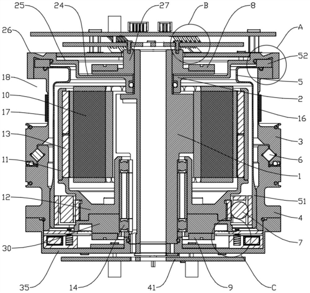
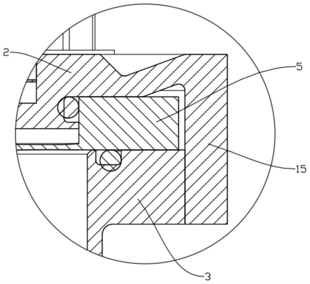
[0061] like Figure 1 to Figure 4 As shown, the compact transmission structure of adjacent joints includes a hollow shaft 1, a power source, a first end cover 2, an outer ring 3, an inner ring 4 and a flexible wheel 5; the fixed end of the power source is sleeved on the hollow shaft The outer side of 1; the first end cover 2 is sleeved on the outer side of the hollow shaft 1, and is rotatably connected with the hollow shaft 1; the inner ring 4 is slidably connected with the outer ring 3 through the roller 6; the flexible wheel 5 is Hat-shaped or U-shaped structure, one end of which is the mouth end 51 and the other end is the bottom end 52; the inner side of the mouth end 51 is connected with the rotating end of the power source through the flexible bearing ...


PUM


Abstract

The invention belongs to the technical field of mechanical joint transmission, and discloses a compact transmission structure of adjacent joints, which is characterized in that a fixed end of a power source sleeves the outer side of a hollow shaft; the first end cover sleeves the outer side of the hollow shaft; the inner ring is in sliding connection with the outer ring through a roller; the inner side of the opening end is connected with the rotating end of the power source through a flexible bearing, and the outer side of the opening end is meshed with the inner ring. The bottom end is pressed between the first end cover and the outer ring; the power source is located on the inner side of the flexible gear. The flexible gear is positioned on the inner sides of the outer ring and the inner ring; the end, close to the bottom end, of the hollow shaft is sleeved with an output end code disc, and the end, close to the opening end, of the hollow shaft is sleeved with a motor end code disc. The problem that an existing integrated joint is long in overall length can be effectively solved, miniaturization and light weight of a robot are achieved, stronger power output is obtained on the basis of miniaturization and light weight, and therefore the larger load-weight ratio is obtained. The invention further discloses a mechanical arm with the transmission structure.

Description

technical field [0001] The invention belongs to the technical field of mechanical joint transmission, and in particular relates to a compact transmission structure of adjacent joints and a mechanical arm. Background technique [0002] In the prior art, since each component in the integrated joint is formed in a coaxial series connection, the length of the entire joint is long, resulting in a large size of the formed robotic arm, which is not conducive to the miniaturization and weight reduction of the robot. The motor is usually located between the harmonic reducer and the brake. Without increasing the overall size of the joint, the size of the motor is limited and cannot obtain greater power output, resulting in the robot being unable to obtain a greater load-to-weight ratio. SUMMARY OF THE INVENTION [0003] In order to solve the above technical problems, the present invention discloses a compact transmission structure of adjacent joints, which can effectively solve the ...

Claims


Application Information

Patent Timeline
Patent Type & Authority Applications(China)
IPC IPC(8): B25J17/02B25J9/12
CPCB25J17/0258B25J9/126Y02P70/10
Inventor 胡天链陈刚
Owner SICHUAN FUDE ROBOT
Why Eureka
Eureka Blog
Learn More