Fan shield and air supply device

A shroud and fan technology, applied in the direction of the power unit, the components of the pumping device for elastic fluid, the arrangement of the cooling combination of the power unit, etc., can solve the problems of poor penetration and slow wind speed, etc.

Pending Publication Date: 2022-08-05
MITSUBA CORP
View PDF15 Cites 0 Cited by
  • Summary
  • Abstract
  • Description
  • Claims
  • Application Information

AI Technical Summary

Problems solved by technology

[0004] Here, in this type of air blower, although the wind speed close to the main shaft can be sufficiently ensured, the wind speed becomes slower the farther away from the main shaft in the radial direction.
Moreover, when the vehicle is running, the fan guard becomes a wall, and the penetration of the running wind passing through the air blower is poor.

Method used


Image

  • Fan shield and air supply device
  • Fan shield and air supply device
  • Fan shield and air supply device

Examples


Embodiment Construction

[0046] Next, embodiments of the present invention will be described based on the drawings.

[0047]

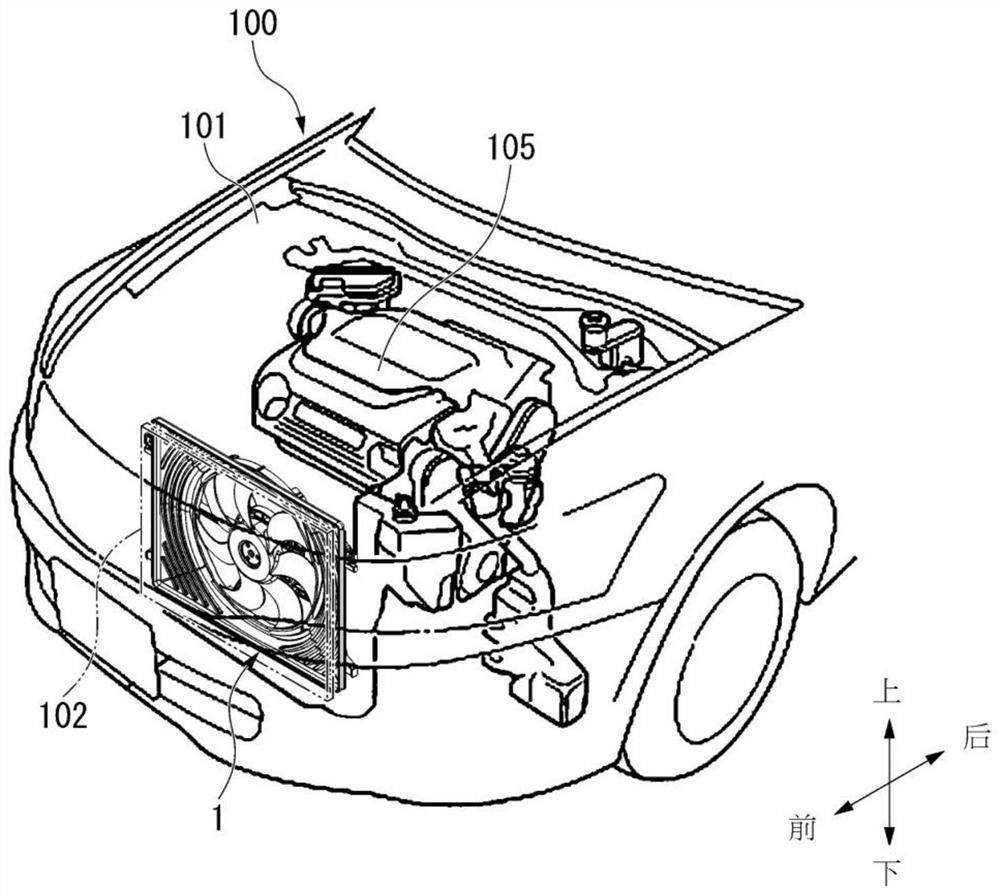
[0048] figure 1 It is a perspective view illustrating the structure of an engine room 101 of a vehicle 100 including the air blower 1 . also, figure 1 For ease of description, the state of passing through the vehicle-mounted heat exchanger 102 (two-dot chain line) is shown.

[0049] The air blower 1 is used to cool the in-vehicle heat exchanger 102 such as a radiator or a condenser of the vehicle 100 . In the following description, the forward direction in the traveling direction of the vehicle 100 is simply referred to as the front, the rear in the traveling direction is simply referred to as the rear, the upper direction in the gravitational direction is simply referred to as the upper direction, and the lower direction in the gravitational direction is simply referred to as the downward direction. In addition, in the following description, the front, the rear, the uppe...


PUM


Abstract

The invention provides a fan shroud and a blower device, which can ensure the wind speed of a part far away from a main shaft in the radial direction when a fan rotates, improve the trafficability of traveling wind when a vehicle travels, and prevent the air volume performance from being reduced. The fan shroud (4) includes: a shroud wall surface (11) extending around the fan in a radial direction orthogonal to the rotation axis; and a plurality of ventilation openings (21) which are formed through the shroud wall surface (11) in the thickness direction of the shroud wall surface (11) and through which the air generated by the fan motor passes. The width (Wa) of the wall surface side opening (21a) on the downstream side of the air flow of the ventilation opening (21) is smaller than the width (Wb) of the transverse wall side opening (21b) on the upstream side of the air flow of the ventilation opening (21).

Description

technical field [0001] The invention relates to a fan shroud and an air supply device. Background technique [0002] For example, for cooling a heat exchanger such as a radiator mounted on a vehicle, an air blower is provided behind the heat exchanger in the traveling direction. The air blower includes a fan motor, a fan attached to a main shaft of the fan motor, and a fan shroud that covers the periphery of the fan. The fan guard is fixed to the vehicle. The fan motor is fixed to the fan guard. As the fan, for example, an axial flow fan can be used. [0003] According to such a configuration, when the fan rotates, air is sucked in from the front in the traveling direction of the heat exchanger by the fan blades, and the air passes through the heat exchanger and the fan in this order. By passing the air through the heat exchanger in this way, cooling of the heat exchanger is promoted. [0004] Here, in such an air blower, although the wind speed at the portion close to ...

Claims


Application Information

Patent Timeline
Patent Type & Authority Applications(China)
IPC IPC(8): F01P3/18F01P11/12F01P11/10F01P11/00
CPCF01P3/18F01P11/12F01P11/10F01P11/00F01P5/06F01P2001/005B60K11/00F04D19/002F04D29/582F04D29/541F04D29/547F05D2260/606F04D29/164F01P1/06B60H1/00464F01P2005/046F04D29/545
Inventor 野中凉太田秀岳
Owner MITSUBA CORP
Why Eureka
Try Eureka