Seat back and seat

A chair back and seat technology, which is applied to chairs, other seating furniture, stools, etc., can solve problems such as affecting the aesthetics of the structure, and achieve the effect of simple and beautiful structure, ingenious design, and simple and advanced appearance.

Pending Publication Date: 2022-08-09
UE FURNITURE CO LTD
View PDF2 Cites 0 Cited by
  • Summary
  • Abstract
  • Description
  • Claims
  • Application Information

AI Technical Summary

Problems solved by technology

The lumbar support of the seat can also be adjusted, but it is obvious that the lumbar support is slidably connected to the support frame through the longitudinal l

Method used


Image

  • Seat back and seat
  • Seat back and seat
  • Seat back and seat

Examples


Embodiment 1

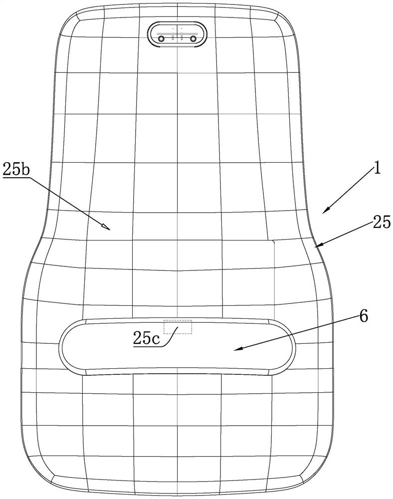
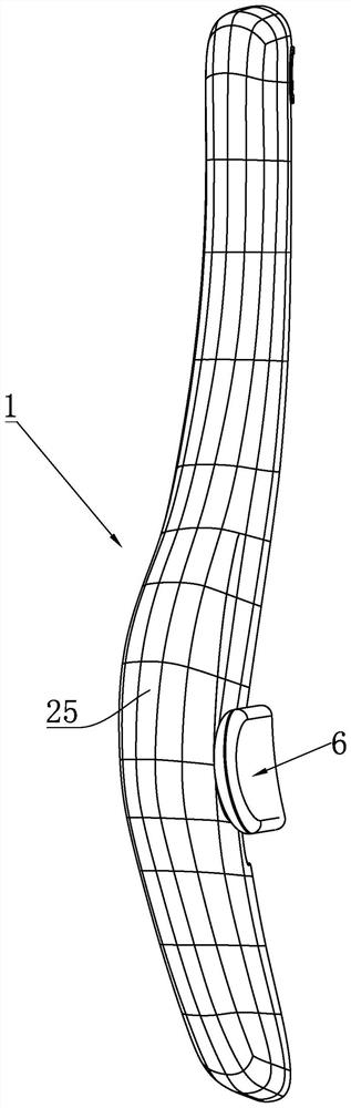
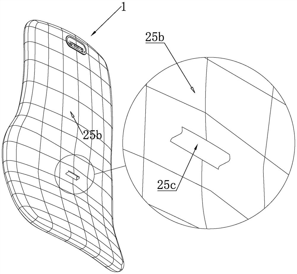
[0056] Example 1: as Figure 1-17 As shown, the present invention provides a seat back and a seat, wherein the seat back includes a seat back assembly 1, a lumbar support 2 disposed in the seat back assembly 1, and a lumbar support 2 exposed in the seat back assembly 1 Hand pallet 6 at the rear. Wherein, the outer surface of the seatback assembly 1 is covered with a seatback covering 25, and the seatback covering 25 includes a front side portion 25a located in front of the seatback assembly 1 and a rear side portion 25b located at the back of the seatback assembly 1; The seat back assembly 1 is provided with an accommodating cavity 4 inside, and the lumbar support 2 is arranged in the accommodating cavity 4 and the front side portion 25a of the seat back covering 25 is placed in front of the lumbar support 2 to play a lumbar support function; The rear side part 25b of the back cover 25 is provided with a gap 25c; a longitudinal adjusting slide plate 5 is connected between the...

Embodiment 2

[0067] Embodiment 2: The difference between this embodiment and Embodiment 1 is that along the height direction of the seat back, the accommodating cavity 4 is formed in the middle position of the seat back assembly 1, and the accommodating cavity 4 runs through the In the seat back assembly 1 (not shown), the accommodating cavity 4 is formed between the front side portion 25a and the rear side portion 25b of the seat back cover. As another embodiment, a part of the front and rear of the middle of the seat back assembly 1 is hollowed out to form the accommodating cavity 4, and after the seat back cover 25 is put on, the front and rear ends of the accommodating cavity 4 can be just surrounded, and the sliding plate 5 can be adjusted. After extending into the gap 25c, the accommodating cavity 4 can be connected to the lumbar support 2, and the lumbar support 2 can directly bear against the front side part 25a of the seat back covering; the structure is very simple. The positioni...


PUM

PropertyMeasurementUnit
Widthaaaaaaaaaa

Abstract

The invention discloses a seat back and a seat. The seat back comprises a seat back assembly, a waist rest arranged in the seat back assembly and a handheld supporting plate exposed out of the rear end of the seat back assembly. The chair back assembly is coated with chair back covering cloth; a containing cavity is formed in the chair back assembly, and the waist rest is arranged in the containing cavity and props against the front side part of the chair back covering cloth to play a waist propping role; a notch is formed in the rear side part of the chair back covering cloth; a longitudinal adjusting sliding plate is connected between the handheld supporting plate and the waist rest, the adjusting sliding plate upwards penetrates into the containing cavity from the notch, and the upper end of the adjusting sliding plate is connected with the waist rest; the part, exposed out of the chair back covering cloth, of the adjusting sliding plate is attached to the rear side part of the chair back covering cloth; the bottom of the adjusting sliding plate is connected with the handheld supporting plate and acts on the handheld supporting plate to move up and down to drive the waist rest to move synchronously. The handheld supporting plate is attached to the rear side part of the chair back covering cloth, and the handheld supporting plate can always cover the notch and the part, exposed out of the chair back covering cloth, of the adjusting sliding plate.

Description

technical field [0001] The invention relates to the field of seating, in particular to a seat back and a seat. Background technique [0002] In modern life, there are more and more types of office furniture, and they emerge in an endless stream, and users have higher and higher functional requirements for office furniture. Among them, the comfort of office chairs plays a key role in the health of office users. [0003] The office chair is a seat with a backrest and armrests. The backrest on the seat is generally upright or inclined. There will be a certain gap between them, and the back of the human body cannot be completely attached to the backrest, which reduces the supporting effect of the backrest on the back of the human body, thereby reducing the comfort of the human body. In order to improve the riding comfort, a protruding cushion, ie, a lumbar support, is generally provided at the seat back near the occupant's waist; the lumbar support is used to support the occupa...

Claims


Application Information

Patent Timeline
IPC IPC(8): A47C7/40A47C7/00
CPCA47C7/402A47C7/004
Inventor 孔航新王柏林汪军雷炳建
Owner UE FURNITURE CO LTD
Why Eureka
Try Eureka