Cooking utensil

A technology of cooking utensils and cooking chambers, which is applied in the direction of steam cooking utensils, cooking utensils, kitchen utensils, etc., which can solve the problems of affecting cooking efficiency, slow water vapor escape, and delaying user time, so as to eliminate food smell and avoid odor. Effect

Pending Publication Date: 2022-08-09
GUANGDONG MIDEA KITCHEN APPLIANCES MFG CO LTD +1
0 Cites 0 Cited by

AI-Extracted Technical Summary

Problems solved by technology

However, water vapor escapes slowly, delaying the user's time
In addition, after steaming/roasting, the smell of the previous dish will remain in the cavity. In order to ensure that the smell does not taint, each time you cook, you need to open the steamer...

Method used

In sum, the application is by setting up fan 40 on cooking utensil 100, and offers air inlet 104 and air outlet 103 on cooking utensil 100, can start fan 40 directly after cooking finishes, will be locked in cooking cavity 30 The high-temperature water vapor and hot air in the air are directly discharged from the air outlet 103, preventing high-temperature steam and hot air from overflowing when the user opens the door body 20, never effectively avoiding contact with the user, and avoiding the potential safety hazard of scalding the user. At the same time, the additional blower fan 40 blows fresh air into the cooking chamber 30 to quickly remove the water vapor in the cooking chamber 30, thereby reducing the condensation of water vapor in the cooking chamber 30. In addition, the air blown into the cavity by the fan 40 can also be used to remove water vapor and food odors, so that the odors and water vapor are discharged with the wind, eliminating the residual food smell in the cooking cavity 30 and avoiding odors.
In the present application, hot air is by blower fan 40 being set on the casing 10 of cooking utensil 100, and the air inlet 104 and air outlet 103 that run through casing 10 and communicate with cooking chamber 30 are set, on the blower fan 40 The air outlet communicates with the air inlet 104. When the cooking utensil 100 finishes cooking, the fan 40 is turned on, so that the fan 40 blows fresh air into the cooking cavity 30 through the air inlet 104, and the high temperature in the cooking cavity 30 is eliminated by convection through the air inlet 104 and the air outlet 103 Water vapor and hot air, so that without opening the door body 20, using the fresh air generated by the fan 40, the high-temperature water vapor and hot air locked in the cooking appliance 100 will be discharged from the cooking appliance 100 through the air outlet 103, which can avoid high temperature. Water vapor and hot air are in contact with the user, thereby avoiding the potential safety hazard o...

Abstract

The invention discloses a cooking utensil which comprises a box body and a door body, the box body is provided with a cooking cavity, the door body is installed on the box body in a pivoted mode and pivots to close or open the cooking cavity, the cooking utensil is characterized in that an air outlet and an air inlet are further formed in the inner wall of the cooking cavity, the air outlet and the air inlet both penetrate through the box body, and the door body is installed on the box body in a pivoted mode. The air outlet and the air inlet are both communicated with the cooking cavity; the cooking utensil further comprises a fan installed on the box body, the fan comprises an air outlet, and the air outlet is communicated with the air inlet. Due to the fact that the fan, the air inlet and the air outlet are additionally arranged on the cooking utensil, high-temperature water vapor and hot air are locked in the cavity of the cooking utensil under the condition that the fan is started without opening the door body after cooking is finished, and then the high-temperature water vapor and the hot air are exhausted through the air outlet and are prevented from making contact with a user. In addition, water vapor and food peculiar smell can be removed through air blown into the cavity by the fan.

Application Domain

Steam cooking vesselsRoasters/grills

Technology Topic

PhysicsMechanical engineering +3

Image

  • Cooking utensil

Examples

  • Experimental program(1)

Example Embodiment

[0017] The technical solutions in the embodiments of the present application will be clearly and completely described below with reference to the drawings in the embodiments of the present application. Obviously, the described embodiments are only a part of the embodiments of the present application, but not all of the embodiments. Based on the embodiments in this application, all other embodiments obtained by those of ordinary skill in the art without creative efforts shall fall within the protection scope of this application.
[0018] Reference herein to an "embodiment" means that a particular feature, structure, or characteristic described in connection with the embodiment can be included in at least one embodiment of the present application. The appearances of the phrase in various places in the specification are not necessarily all referring to the same embodiment, nor a separate or alternative embodiment that is mutually exclusive of other embodiments. It is explicitly and implicitly understood by those skilled in the art that the embodiments described herein may be combined with other embodiments.
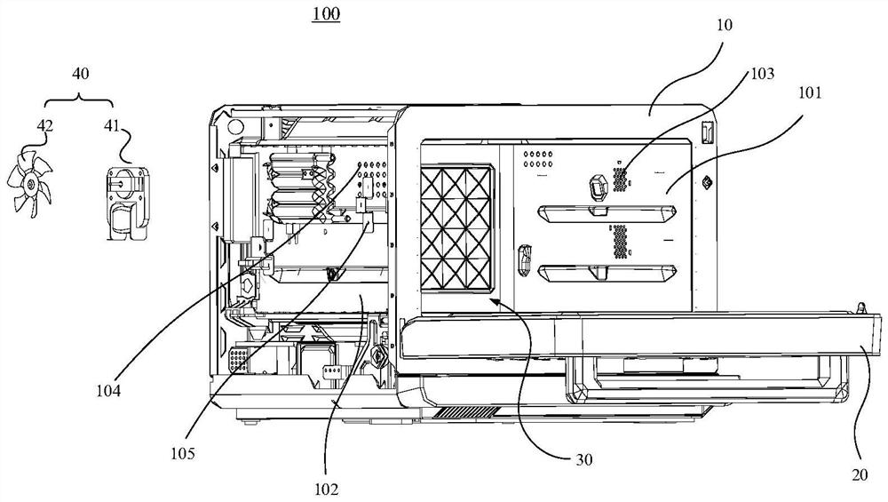
[0019] see figure 1 , to specifically describe the cooking appliance 100 of the present application. It can be understood that the cooking appliance 100 includes, but is not limited to, an oven, a steamer, and an integrated device for steaming and baking.
[0020] The cooking appliance 100 provided in the embodiment of the present application includes a box body 10 , a door body 20 , and a fan 40 disposed on the box body 10 .
[0021] The cabinet 10 is provided with a cooking cavity 30 , and the door 20 is pivotally mounted on the cabinet 10 and pivoted to close or open the cooking cavity 30 .
[0022] Wherein, the inner wall of the cooking cavity 30 is further provided with an air outlet 103 and an air inlet 104, the air outlet 103 and the air inlet 104 both penetrate the box 10, and both the air outlet 103 and the air inlet 104 communicate with the cooking cavity 30; The fan 40 includes an air outlet, and the air outlet communicates with the air inlet 104 .
[0023] In the present application, the hot air is obtained by arranging the fan 40 on the cabinet 10 of the cooking appliance 100 , and setting the air inlet 104 and the air outlet 103 which penetrate through the cabinet 10 and communicate with the cooking cavity 30 , and the air outlet on the fan 40 It communicates with the air inlet 104 . When the cooking appliance 100 finishes cooking, the fan 40 is turned on, so that the fan 40 blows fresh air into the cooking cavity 30 through the air inlet 104 , and the high temperature in the cooking cavity 30 is removed by convection through the air inlet 104 and the air outlet 103 . water vapor and hot air, so that without opening the door body 20, the fresh air generated by the fan 40 is used to discharge the high-temperature water vapor and hot air locked in the cooking appliance 100 out of the cooking appliance 100 through the air outlet 103, so as to avoid high temperature The contact of water vapor and hot air with the user can avoid the safety hazard of scalding the user. In addition, the air blown into the cavity by the fan 40 can also be used to remove water vapor and food odor, so that the odor and water vapor are removed with the wind flow, eliminating the residual food odor in the cooking cavity 30 and avoiding odor.
[0024] The box 10 includes a first side wall 101 and a second side wall 102 that enclose the cooking cavity 30 , the first side wall 101 and the second side wall 102 are arranged opposite to each other, and the air outlet 103 is arranged on the inner wall surface of the first side wall 101 and Passing through the first side wall 101 , the air inlet 104 is disposed on the inner wall surface of the second side wall 102 and passes through the second side wall 102 .
[0025] Preferably, the first side wall 101 is the right side wall of the cooking appliance 100, the second side wall 102 is the left side wall of the cooking appliance 100, the left and right side walls are in opposite positions, and the air outlet 103 is provided on the inner wall surface of the right side wall and Passing through the right side wall, the air inlet 104 is provided on the inner wall surface of the left side wall and penetrates the left side wall. It can be understood that, in some embodiments, the first side wall 101 may be a left side wall, an upper side wall, a lower side wall, and a bottom side wall, and the second side wall 102 may be a right side wall, an upper side wall, a lower side wall, and a bottom side wall. The side wall and the bottom side wall may be any of the side walls where the air inlet 104 and the air outlet 103 are provided. Up, down, left, and right are relative positions in space, and do not limit the shape of the cooking utensil 100 .
[0026] In some embodiments, along a direction perpendicular to the first side wall 101 and the second side wall 102 , the air inlet 104 and the air outlet 103 are located on the same plane. Taking the first side wall 101 as the right side wall of the cooking appliance 100 and the second side wall 102 as the left side wall of the cooking appliance 100 as an example, when the cooking appliance 100 is placed horizontally, the air outlet provided on the right side wall The distance between 103 and the horizontal plane is equal to the distance between the air inlet 104 arranged on the left side wall and the horizontal plane, or the air outlet 103 arranged on the right side wall and the air inlet 104 arranged on the left side wall are located perpendicular to the right side. On the side wall and on the same plane as the left side wall. When the position of the air outlet 103 provided on the right side wall and the air inlet 104 provided on the left side wall are aligned rather than staggered in height, it is beneficial to form ventilation convection and increase the discharge speed of the air outlet 103, Effectively avoid the slowdown of wind speed.
[0027] In some embodiments, the air inlet 104 may also be located below the air outlet 103 along the vertical direction. Similarly, the first side wall 101 is the right side wall of the cooking appliance 100 and the second side wall 102 is the left side wall of the cooking appliance 100 as an example. When the cooking appliance 100 is placed horizontally, along the direction perpendicular to the horizontal plane, The distance from the air inlet 104 to the horizontal plane is greater than the distance from the air outlet 103 to the horizontal plane. When the air outlet 103 provided on the right side wall and the air inlet 104 provided on the left side wall are at different heights, it is beneficial to extend the exhaust path.
[0028] The cooking appliance 100 further includes a mounting bracket 105 for fixing the fan 40 on the casing 10 of the cooking appliance 100 . It can be understood that the air outlet of the fan 40 can also be connected to the air inlet 104 through the air duct, that is to say, the installation position of the fan 40 may not be the same as the installation position of the air inlet 104, and the installation position of the fan 40 may be the first. The first side wall 101, the second side wall 102, or other cavity walls of the cooking appliance 100 are not specifically limited herein.
[0029]Preferably, the mounting bracket 105 is fixed on the second side wall 102 , and the fan 40 includes a motor 41 and an impeller 42 mounted on the motor 41 . That is, both the fan 40 and the air inlet 104 are installed on the second side wall 102 , so that the air outlet of the fan 40 can be directly communicated with the air inlet 104 . The fan 40 uses the motor 41 to drive the impeller 42 installed on the motor 41 to rotate to form fresh air, and communicates with the air inlet 104 through the air outlet of the fan 40, so that the fresh air enters the cooking cavity 30, and the high temperature water in the cooking cavity 30 is discharged. The steam and hot air are discharged out of the cooking appliance 100 through the air outlet 103 .
[0030] In the above embodiment, the air inlet 104 and the air outlet 103 are a plurality of mesh holes evenly arranged. Preferably, when the cooking utensil 100 is an oven or the like and the airtightness requirements are not very high, and the air inlet 104 and the air outlet 103 do not have other special treatments, the uniformly arranged air inlets 104 and air outlets 103 The mesh aperture is preferably 6 mm, so that when the cooking appliance 100 is cooking, the opened air inlet 104 and the air outlet 103 do not affect the cooking effect of the cooking appliance 100 .
[0031] In some embodiments, the included angle between the center line of each air inlet 104 and the inner wall of the second side wall 102 is 40°˜75°. Preferably, the included angle between the center line of each air inlet 104 and the inner wall of the second side wall 102 is 60°. Preferably, when the air outlet 103 and the air inlet 104 are a plurality of mesh holes evenly arranged, the angle between the center line of the aperture of each mesh hole and the inner wall of the second side wall 102 is 60°. Therefore, the air exhaust path can be increased by setting the relative angle position between the center line of each air inlet 104 and the second side wall 102 .
[0032] It can be understood that, so far, two ways to adjust the exhaust path have been described, including by setting the relative height positions of the air inlet 104 and the air outlet 103, and by adjusting the centerline of the air inlet 104 and the second side wall relative position between 102. The above two ways can be implemented individually or combined. In an embodiment of a combined design, along the direction perpendicular to the first side wall 101 and the second side wall 102, the air inlet 104 and the air outlet 103 are located on the same plane, and the centerline of the air inlet 104 is the same as the The included angle of the inner wall of the second side wall 102 is 40°˜75°. In an embodiment of a combined design, the air inlet 104 is located below the air outlet 103 along the vertical direction, and the angle between the center line of the air inlet 104 and the inner wall of the second side wall 102 is 40°˜75°.
[0033] In some embodiments, further special treatment can be performed on the air inlet 104 and the air outlet 103 provided on the side wall of the cooking appliance 100 . In order to increase the sealing performance of the cooking appliance 100 as a whole.
[0034] Specifically, the cooking utensil 100 further includes a cover member pivotally installed or detachably installed on the box body 10 , and the cover member can be operated to close or open the air inlet 104 and the air outlet 103 . The function of the shutter is mainly to cover and seal the air inlet 104 and the air outlet 103 when the cooking utensil 100 is cooking, and when the fan 40 is turned on after cooking, the shutter can cancel the air inlet 104 and the air outlet 103. The shielding effect of the air outlet 103 . Specifically, the shutter may be a one-way valve.
[0035] In some embodiments, the cooking appliance 100 also includes a controller. The controller can control the cooking utensil 100 to cook, and automatically start the fan 40 after the cooking is completed, so as to perform the discharge operation of high-temperature steam and hot air.
[0036] The cooking utensil 100 further includes a timing device or a temperature sensing device; the fan 40, the timing device or the temperature sensing device are all connected to the controller; the controller can control the obtained temperature data according to the preset data of the timing device or the temperature sensing device. The fan 40 is turned off or on.
[0037] Hereinafter, the shutdown of the fan 40 will be further described.
[0038] In one embodiment, after the cooking utensil 100 is finished cooking and the fan 40 is turned on, the fan 40 may be turned off through time data of the timing device or temperature data of the temperature sensing device. Specifically, the fan 40 can be turned off by the controller when the predetermined time set by the timing device is reached through the timing device of the cooking utensil 100 . The temperature in the cooking cavity 30 can also be acquired through the temperature sensing device in the cooking appliance 100, and the fan 40 can be turned off by the controller when the detected temperature is lower than the predetermined temperature.
[0039] In some embodiments, the time to turn off the fan 40 may be when the high-temperature steam or hot air in the cooking cavity 30 drops to such an extent that even if the door 20 of the cooking cavity 30 is opened, the escaped steam and hot air will not cause a risk of burns to the user fan 40 is turned off. The time for turning off the fan 40 may be preset in the timing device according to the power of the fan 40, or may be determined by the data collected by the temperature sensor. It can be understood that when only the fan 40 and the air inlet 104 and the air outlet 103 are used to process the hot air and high-temperature steam in the cooking cavity 30, when the temperature in the cooking cavity 30 has not dropped to a safe temperature, the user cannot. The door body 20 of the cooking appliance 100 is opened, so as to effectively prevent the user from being scalded by the escaping steam or hot air.
[0040] Further, in some embodiments, the time to turn off the fan 40 may be until there is no steam in the cooking cavity 30 . That is, when the high-temperature steam or hot air in the cooking cavity 30 drops to the door 20 that can open the cooking cavity 30, the door 20 can be opened. At this time, after the door 20 is opened, the hot air and steam in the cooking cavity 30 are completed. The blower 40 still works; the blower 40 and the open door body 20 can be used to remove the high-temperature steam and hot air. In this way, the steam and hot air in the cooking cavity 30 can be removed more quickly and effectively, so as to effectively solve the problem that the cooking cavity 30 is easy to condense and generate water, and the taste of the original dishes in the cooking cavity 30 can be effectively solved. Discharge to prevent odor.
[0041] To sum up, in the present application, by adding a fan 40 on the cooking appliance 100, and opening the air inlet 104 and the air outlet 103 on the cooking appliance 100, the fan 40 can be started directly after the cooking is completed, and the high temperature in the cooking cavity 30 can be locked. Water vapor and hot air are directly discharged from the air outlet 103 to prevent high temperature steam and hot air from overflowing when the user opens the door body 20, never effectively avoid contact with the user, and avoid the potential safety hazard of scalding the user. At the same time, the additional fan 40 blows fresh air into the cooking cavity 30 to quickly remove the water vapor in the cooking cavity 30 , thereby reducing the condensation of the water vapor in the cooking cavity 30 . In addition, the air blown into the cavity by the fan 40 can also be used to remove water vapor and food odor, so that the odor and water vapor are discharged with the wind flow, eliminating the residual food odor in the cooking cavity 30 and avoiding odor.
[0042] The terms "first", "second" and "third" in this application are only used for descriptive purposes and should not be understood as indicating the number of indicated technical features. Thus, a feature defined as "first", "second", "third" may expressly or implicitly include at least one of that feature. All directional indications (such as up, down, left, right, front, rear...) in the embodiments of the present application are only used to explain the relative positional relationship between components under a certain posture (as shown in the accompanying drawings). , motion situation, etc., if the specific posture changes, the directional indication also changes accordingly. Furthermore, the terms "comprising" and "having" and any variations thereof are intended to cover non-exclusive inclusion. For example, a process, method, system, product or device that includes a series of steps or units is not limited to the listed steps or units, but optionally also includes unlisted steps or units, or optionally also includes For other steps or units inherent to these processes, methods, products or devices.
[0043] The above are only the embodiments of the present application, and are not intended to limit the scope of the patent of the present application. Any equivalent structure or equivalent process transformation made by using the contents of the description and drawings of the present application, or directly or indirectly applied to other related technologies Fields are similarly included within the scope of patent protection of this application.

PUM

no PUM

Description & Claims & Application Information

We can also present the details of the Description, Claims and Application information to help users get a comprehensive understanding of the technical details of the patent, such as background art, summary of invention, brief description of drawings, description of embodiments, and other original content. On the other hand, users can also determine the specific scope of protection of the technology through the list of claims; as well as understand the changes in the life cycle of the technology with the presentation of the patent timeline. Login to view more.

Similar technology patents

Multifunctional cooking range

InactiveCN104323718Aeasy to useavoid odor
Owner:佛山市翔德工业设计有限公司

Electric steamer

InactiveCN103271638Aavoid odorImprove taste
Owner:应昶均

Automatic wiping and dehumidifying device for PVC film collection and storage

InactiveCN112622124Aavoid odorsave human effort
Owner:温州瀚举电子商务有限公司

Low-melting point polyester composite fabric

InactiveCN109263190Aavoid odorhigh tensile strength
Owner:嘉善中帛针纺有限公司

Cleaning machine system with base station

PendingCN114652215Aavoid odor
Owner:NINGBO FOTILE KITCHEN WARE CO LTD

Classification and recommendation of technical efficacy words

  • avoid odor

Self-adaptive deodorization intelligent garbage can

ActiveCN109319347Aavoid odor
Owner:广东数智化信息服务有限公司

Fermented material for agaricus bisporus production and preparation method of fermented material

InactiveCN111771618Aavoid odorreduce pollution
Owner:JIANGSU YUGUAN MODERN AGRI S AND T CO LTD

Household cleaning-free dining table

ActiveCN113040518Aavoid odor
Owner:于春伟
Why Eureka
Try Eureka