Automatic maintenance device for concrete member

A technology for concrete and components, applied in spraying devices, ceramic molding machines, manufacturing tools, etc., can solve the problems of adjustment, vertical wall spraying maintenance spraying range, etc. Effect

Pending Publication Date: 2022-08-09
THE FIRST COMPARY OF CHINA EIGHTH ENG BUREAU LTD
View PDF0 Cites 0 Cited by
  • Summary
  • Abstract
  • Description
  • Claims
  • Application Information

AI Technical Summary

Problems solved by technology

[0005] The purpose of the present invention is to provide an automatic maintenance device for concrete com

Method used


Image

  • Automatic maintenance device for concrete member
  • Automatic maintenance device for concrete member
  • Automatic maintenance device for concrete member

Examples


Example Embodiment

[0030] Example 1:

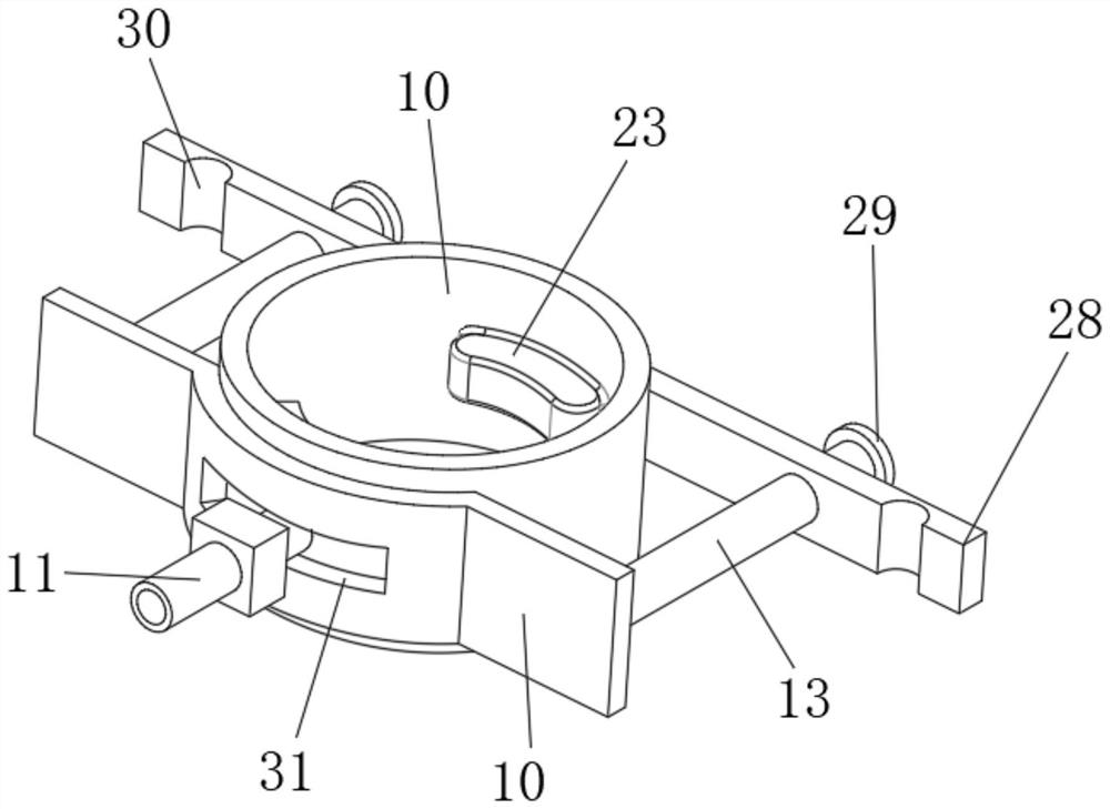
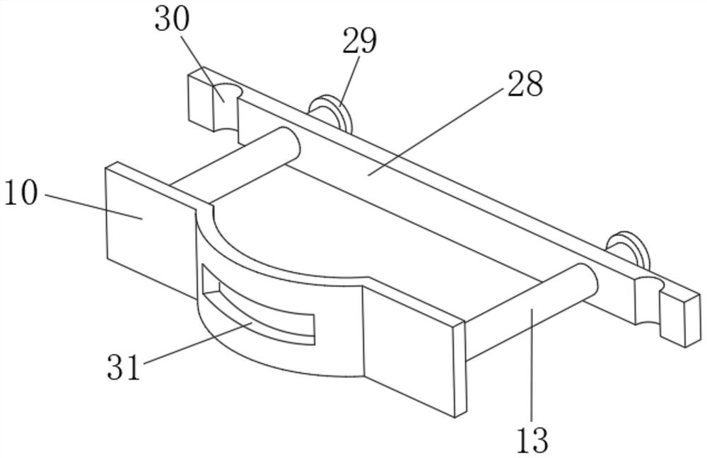
[0031] An automatic curing device for concrete components, the curing device includes a water inlet pipe 1, an adjustment component, a clamping component and a lifting component.

[0032] The water inlet pipe 1 is arranged in parallel with the vertical wall, and the outer wall of the water inlet pipe 1 is provided with a clamping sleeve 2, the water inlet pipe 1 and the clamping sleeve 2 are fastened and clamped, and the outer wall of the clamping sleeve 2 is fixed on the connecting rod 3. On the wall, through the cooperation of the clamping sleeve 2 and the connecting rod 3, the line of sight water inlet pipe 1 and the wall are fixed in parallel and vertically.

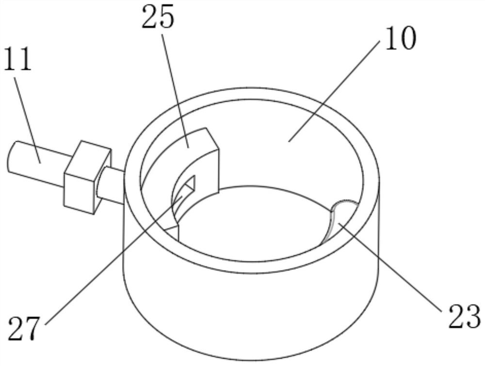
[0033] The adjustment assembly includes a fixed plate 9 and a rotating sleeve 10. The fixed plate 9 is fixed on the outer wall of the water inlet pipe 1. The rotating sleeve 10 is coaxially sleeved on the outer wall of the water inlet pipe 1. The outer side of the rotating sleeve 10 is provided wi...

Example Embodiment

[0039] Example 2:

[0040]On the basis of Embodiment 1, in order to limit the rotation angle of the spray head 11 , the present application further includes a rotating arc groove 31 on the clamping arc plate 12 , and the clamping arc plate 12 is inserted into the spray head 11 through the rotating arc groove 31 . The spray head 11 rotates and adjusts along the rotating arc groove 31 .

[0041] The rotation angle of the spray head 11 is limited by setting the rotating arc groove 31 , so as to avoid the excessive rotation of the rotating sleeve 11 and the separation of the rubber pressing block 25 from the water outlet hole 26 .

Example Embodiment

[0042] Example 3:

[0043] On the basis of Example 2, in order to further limit the rotation angle and avoid the extrusion of the spray head 11 and the rotating arc groove 31 during the rotation process, so that the spray head 11 is broken, the present application also has a space between the rotating sleeve 10 and the water inlet pipe 1 . There is a circular inner cavity, the rubber pressing plate 25 and the air bag 23 are located in the inner cavity of the circular ring, a pair of limit posts 24 are arranged on the fixed plate 9, and the limit posts 24 are located on the front and rear sides of the air bag 23, and The column 24 is vertically installed in the inner cavity of the ring, and the arc angle between the symmetrically distributed pair of limiting columns 24 is smaller than the arc angle of the rotating arc groove 31 .

[0044] The rotation angle of the airbag 23 is limited by the limit post 24, and then during the rotation of the rotating sleeve 10, the airbag 23 sq...


PUM


Abstract

The invention relates to the technical field of concrete wall surface water spraying maintenance, in particular to an automatic concrete member maintenance device which comprises a water inlet pipe, an adjusting assembly, a clamping assembly and a lifting assembly.The automatic concrete member maintenance device has the beneficial effects that through cooperation of a vertical pipe and a spray head, water spraying maintenance on a vertical wall surface is achieved; meanwhile, rotation adjustment of the spray head is achieved through the adjusting assembly, the rotation angle of the spray head is fixed through the clamping assembly, the purpose of conveniently adjusting the rotation angle of the spray head is achieved in cooperation with the lifting assembly, and therefore the spraying range of the spray head is adjusted, and manual pipeline dragging is avoided; and the coverage degree and efficiency of wall maintenance are improved by increasing the spraying range.

Description

technical field [0001] The invention relates to the technical field of water spray curing for concrete walls, in particular to an automatic curing device for concrete components. Background technique [0002] At present, the most common building structures are reinforced concrete structures. In the construction process of reinforced concrete structures, concrete curing is an essential process. [0003] If the concrete is not properly maintained, the strength of the concrete will not meet the standard, the appearance will shrink and crack, the internal structure will be loose, and the impermeability will be poor, which will eventually lead to serious quality accidents. [0004] The existing concrete curing method is to manually use water pipes to water the concrete intervals, and the concrete curing on the horizontal plane can be carried out smoothly. It is difficult to achieve. Due to the vertical installation, it is difficult to realize the rotation adjustment of the angle...

Claims


Application Information

Patent Timeline
IPC IPC(8): B28B11/24B05B15/68B05B12/16
CPCB28B11/245B05B15/68B05B12/16
Inventor 李蕾陈进财孙金辉郭利吴忠祥于峰左王亚坤叶舟
Owner THE FIRST COMPARY OF CHINA EIGHTH ENG BUREAU LTD
Why Eureka
Try Eureka