Optical system, camera module and electronic equipment
An optical system, optical axis technology, used in optics, optical components, instruments, etc.
- Summary
- Abstract
- Description
- Claims
- Application Information
AI Technical Summary
Problems solved by technology
Method used
Image

Examples
no. 1 example
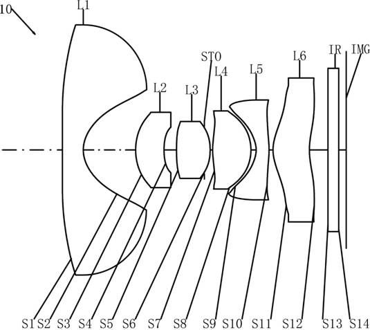
[0060] Please refer to figure 1 and figure 2 , The optical system 10 of this embodiment, the side of the object along the direction of the optical axis to the sidewalk includes:
[0061] The first mirror L1 has negative flexion. The side S1 of the first mirror L1 is concave at the near -light shaft, and the side S2 is the concave surface at the near -light shaft.
[0062]The second lens L2 has a positive flexion. The side S3 of the second lens L2 is the convex surface at the proximal shaft, and the sida s4 is the concave surface at the near -light shaft.
[0063] The third lens L3 has positive flexion. The side S5 of the third lens L3 is the convex surface at the near -light shaft, and the side S6 is the convex surface at the near -light shaft.
[0064] The fourth lens L4 has positive flexion. The side S7 of the fourth lens L4 is the convex surface at the proximal shaft, and the side S8 is the convex surface at the near -light shaft.
[0065] The fifth lens L5 has negative flexion...
no. 2 example
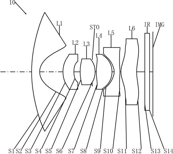
[0082] Please refer to image 3 and Figure 4 , The optical system 10 of this embodiment, the side of the object along the direction of the optical axis to the sidewalk includes:
[0083] The first mirror L1 has negative flexion. The side S1 of the first mirror L1 is the convex surface at the near -light shaft, and the side S2 is the concave surface at the near -light shaft.
[0084] The second lens L2 has negative flexion. The side S3 of the second lens L2 is the convex surface at the near -light shaft, and the sida s4 is concave at the near -light shaft.
[0085] The third lens L3 has positive flexion. The side S5 of the third lens L3 is the convex surface at the near -light shaft, and the side S6 is the convex surface at the near -light shaft.
[0086] The fourth lens L4 has positive flexion. The side S7 of the fourth lens L4 is the convex surface at the proximal shaft, and the side S8 is the convex surface at the near -light shaft.
[0087] The fifth lens L5 has negative flexion...
no. 3 example
[0098] Please refer to Figure 5 and Image 6 , The optical system 10 of this embodiment, the side of the object along the direction of the optical axis to the sidewalk includes:
[0099] The first mirror L1 has negative flexion. The side S1 of the first mirror L1 is the convex surface at the near -light shaft, and the side S2 is the concave surface at the near -light shaft.
[0100] The second lens L2 has a positive flexion. The side S3 of the second lens L2 is the convex surface at the proximal shaft, and the sida s4 is the concave surface at the near -light shaft.
[0101] The third lens L3 has positive flexion. The side S5 of the third lens L3 is the convex surface at the near -light shaft, and the side S6 is the convex surface at the near -light shaft.
[0102] The fourth lens L4 has positive flexion. The side S7 of the fourth lens L4 is the convex surface at the proximal shaft, and the side S8 is the convex surface at the near -light shaft.
[0103] The fifth lens L5 has negat...
PUM
 Abstract
Description
Claims
Application Information
 - R&D
- Intellectual Property
- Life Sciences
- Materials
- Tech Scout
- Unparalleled Data Quality
- Higher Quality Content
- 60% Fewer Hallucinations
Browse by: Latest US Patents, China's latest patents, Technical Efficacy Thesaurus, Application Domain, Technology Topic, Popular Technical Reports.
© 2025 PatSnap. All rights reserved.Legal|Privacy policy|Modern Slavery Act Transparency Statement|Sitemap|About US| Contact US: help@patsnap.com