
Multi-channel voltage sensing circuit for pixel compensation

A voltage sensing and channel circuit technology, applied in static indicators, instruments, etc., can solve the problems that channel circuits are difficult to have sensing characteristics, and it is difficult to perform compensation accurately, so as to achieve stable offset value, ensure reliability, and uniform The effect of sensing characteristics

Pending Publication Date: 2022-08-09
LX SEMICON CO LTD
View PDF0 Cites 0 Cited by
  • Summary
  • Abstract
  • Description
  • Claims
  • Application Information

AI Technical Summary

Problems solved by technology

[0022] Therefore, due to the above reasons, it is difficult for channel circuits forming a driver of a plurality of channels to have uniform sensing characteristics, and as a result, it may be difficult to accurately perform compensation for compensating display data for pixel characteristics.

Method used


Image

  • Multi-channel voltage sensing circuit for pixel compensation
  • Multi-channel voltage sensing circuit for pixel compensation
  • Multi-channel voltage sensing circuit for pixel compensation

Examples


Embodiment Construction

[0036] The display system may include a display panel, a driver and a timing controller.

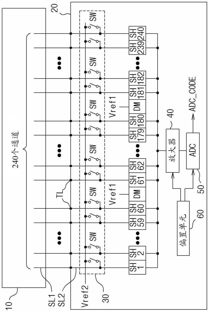
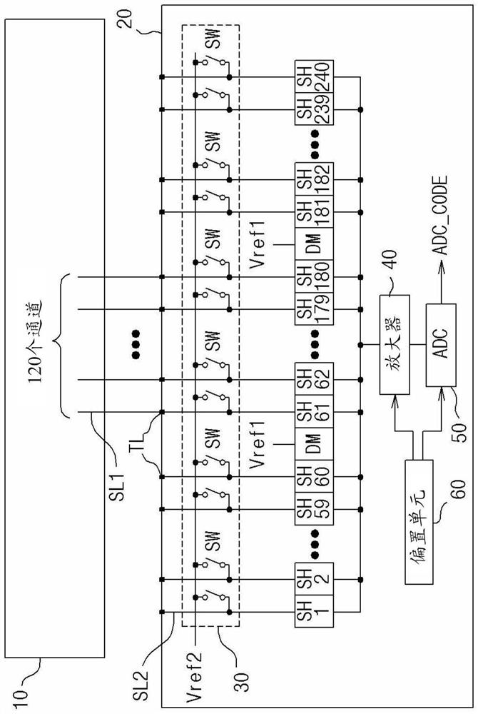
[0037] figure 1 is a circuit diagram for explaining the embodiment of the present disclosure, and in order to explain the embodiment of the present disclosure, the figure 1 The display panel 10 and the driver 20 are shown in .

[0038] The display panel 10 may be exemplified as a panel in which pixels (not shown) are configured by OLEDs. The pixels may be formed in a matrix structure on the display panel 10 .

[0039] The driver 20 provides a source driving signal (not shown) to the display panel 10, and the pixels of the display panel 10 emit light in response to the source driving signal. The image represented by the display data can be displayed by the light emission of the pixels.

[0040] In the detailed description of the present disclosure, illustration and description of the configuration in which the driver 20 supplies the source driving signal to the display panel 10 and th...


PUM


Abstract

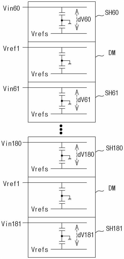
The multi-channel voltage sensing circuit for pixel compensation includes: a plurality of channel circuits provided for a plurality of channels; and first and second dummy channel circuits disposed between the plurality of channel circuits, with some of the channel circuits interposed between the first and second dummy channel circuits, where the first and second dummy channel circuits receive a first reference voltage of a fixed level, and the first and second dummy channel circuits receive a second reference voltage of a fixed level. And provide an electrical connection with an adjacent channel circuit.

Description

technical field [0001] Various embodiments relate generally to compensating pixels of a display panel, and more particularly, to a multi-channel voltage sensing circuit for pixel compensation that is improved for sensing a display panel The multi-channel channel circuit of the pixel signal has uniform sensing characteristics. Background technique [0002] The display system includes a display panel, a driver and a timing controller. [0003] The driver converts the digital display data provided from the timing controller into analog source driving signals, and provides the source driving signals to the display panel. The driver is configured by a chip. [0004] The number of drivers configured in the display system may be determined in consideration of the size and resolution of the display panel. [0005] The display panel may be configured by an OLED panel. The OLED panel includes pixels configured by OLEDs. In this case, there may be deviations in electrical characte...

Claims


Application Information

Patent Timeline
Patent Type & Authority Applications(China)
IPC IPC(8): G09G3/3208G09G3/00
CPCG09G3/3208G09G3/006G09G2320/0233G09G2320/029G09G2310/027G09G2320/045G09G3/3275G09G2310/0294G09G3/3258G09G2300/0828G09G2300/0876G09G3/20G09G2300/0413
Inventor 朴太明金元金成根申永浩李边澈
Owner LX SEMICON CO LTD
Learn More