Method and device for generating reactive compensation configuration scheme of power plant station

A configuration scheme and technology for generating devices, applied in reactive power compensation, reactive power adjustment/elimination/compensation, system integration technology, etc., can solve problems such as long interval time and low efficiency, and achieve the effect of solving long interval time

Pending Publication Date: 2022-08-09
CHINA SOUTH POWER GRID ELECTRIC POWER RES INST +1
0 Cites 0 Cited by

AI-Extracted Technical Summary

Problems solved by technology

[0004] This application provides a method and device for generating reactive power compensation configuration schemes in electric power plants, which are used to solve the ...

Abstract

The invention discloses a method and a device for generating a reactive power compensation configuration scheme of a power plant station, and the method comprises the steps: taking a historical reactive power configuration scheme as a reference, and employing a data mining technology to summarize typical reactive power configuration schemes under historical load information conditions in different periods; when the reactive power compensation configuration scheme of the power plant station needs to be adjusted, the planned load information of the target station in the estimated period is used as the input quantity of the reactive power configuration calculation model, and the reactive power compensation configuration scheme suitable for the target station can be obtained through the operation of the reactive power configuration calculation model. The technical problems of long time interval and low efficiency of a configuration scheme from a planning stage to a practical application stage are solved.

Application Domain

Character and pattern recognitionReactive power adjustment/elimination/compensation +1

Technology Topic

Computational modelSystems engineering +4

Image

  • Method and device for generating reactive compensation configuration scheme of power plant station
  • Method and device for generating reactive compensation configuration scheme of power plant station
  • Method and device for generating reactive compensation configuration scheme of power plant station

Examples

  • Experimental program(1)

Example Embodiment

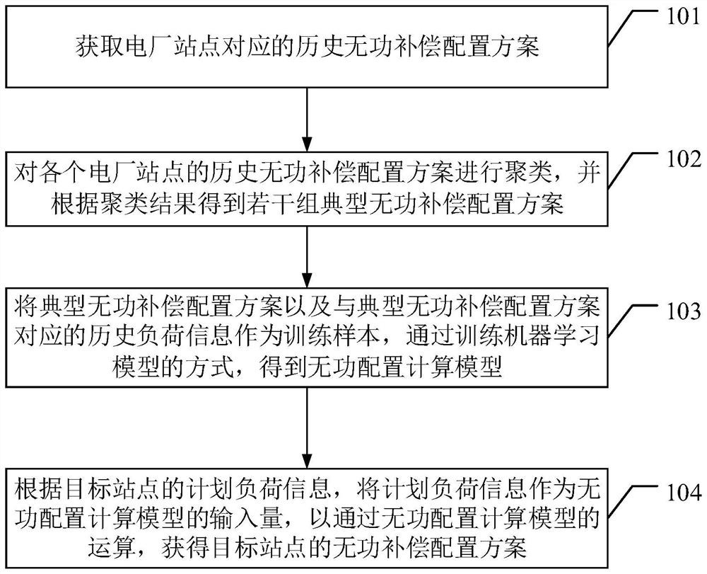
[0033] The embodiments of the present application provide a method and device for generating a reactive power compensation configuration scheme of a power plant, which are used to solve the technical problem of a long time interval and low efficiency in the existing configuration scheme method from the planning stage to the implementation stage.
[0034] In order to make the purpose, features and advantages of the invention of the present application more obvious and understandable, the technical solutions in the embodiments of the present application will be clearly and completely described below with reference to the accompanying drawings in the embodiments of the present application. Obviously, the following The described embodiments are only some, but not all, embodiments of the present application. Based on the embodiments in the present application, all other embodiments obtained by those of ordinary skill in the art without creative work fall within the protection scope of the present application.
[0035] First, the first embodiment of the present application provides a detailed description of a method for generating a reactive power compensation configuration scheme for a power plant, as follows:
[0036] see figure 1 and figure 2 , a method for generating a reactive power compensation configuration scheme for a power plant station provided by this embodiment includes:
[0037] Step 101: Obtain a historical reactive power compensation configuration scheme corresponding to the power plant site.
[0038] First, by collecting the electrical information of historical measurement records of each power plant site, the electrical information includes the historical active load value, historical reactive power load value, and historical reactive power compensation configuration of the site. The historical measurement records come from the statistics and statistics of the electrical automation system. State estimation. The collected relevant information is stored in the database or formed into a ledger table for backup. The data recording method can refer to the above table:
[0039] Table 1 Summary of historical electrical information for each power plant site
[0040]
[0041]
[0042] In the table, Pm-n represents the active load value in plant n at time m, Qm-n represents the reactive load value in plant n at time m, and Cm-n represents the reactive power compensation configuration in plant n at time m .
[0043] The historical reactive power compensation configuration scheme corresponding to the power plant site can be obtained according to the historical reactive power compensation configuration. From the obtained historical record table, the reactive power compensation configuration C of each power plant is queried and extracted to form reactive power compensation. The configuration scheme vector matrix is ​​as follows:
[0044] Table 2 Summary of historical reactive power compensation configuration schemes for each power plant site
[0045]
[0046] Each row in the table is the reactive power configuration scheme at that moment.
[0047] Step 102: Cluster the historical reactive power compensation configuration schemes of each power plant site, and obtain several groups of typical reactive power compensation configuration schemes according to the clustering results.
[0048] By constructing a clusterer, the AP clusterer is trained unsupervised with the historical reactive power compensation configuration scheme data formed in step 101 as the clustering data training set, and the cluster center is taken as the typical reactive power configuration scheme. The set of typical reactive power configuration schemes can be represented in the following table:
[0049] Table 3 The typical set of reactive power configuration schemes obtained by cluster mining
[0050]
[0051] The reactive power allocation schemes of k typical moments in the table may represent the historical reactive power allocation schemes of all m moments in step 101 (k
[0052]Further, the clusterer constructed in this embodiment is preferably an AP clusterer, and the AP clusterer is an intelligent clustering algorithm based on representative points, which can obtain better results than traditional clustering algorithms on most data sets. For better clustering results, in the clustering process, there is no need to manually set the initial representative point set, the number of clusters, etc. The AP clusterer creates clusters by computing similarities between pairs of data until convergence. The entire dataset is then described using a small number of cluster centers, which are determined to be typical of the other data. Messages sent between data pairs indicate whether one data is suitable as a representative of the other, and the representative updates the similarity based on the values ​​of the other data pairs. This update iteration is continued until the convergence position, at which time the final representative is selected, which is the final cluster center. The similarity is usually calculated by the inverse of the Euclidean distance between two data points. The closer the Euclidean distance of the two data points, the higher the similarity. The clustering algorithm has a relatively mature open source implementation scheme, and can be invoked and implemented in various software development tools.
[0053] Step 103 , using the typical reactive power compensation configuration scheme and the historical load information corresponding to the typical reactive power compensation configuration scheme as training samples, and obtain a reactive power configuration calculation model by training a machine learning model.
[0054] Next, take the typical reactive power configuration scheme generated in step 102 as a label, and query the load information corresponding to the typical moment from the load information data (historical active load value, historical reactive power load value) in the obtained electrical information as features for model training. The purpose of the supervised learning method is to calculate and learn the mapping pattern between the data input and output through the algorithm, and construct the mapping pattern from the input to the output. Using the matched feature and label data pair in step 103 as a training set of classification data, an SVM (Support Vector Machine) classifier is constructed, and the SVM classifier is supervised with the training set.
[0055] The SVM classifier is a very mature machine learning classification algorithm that provides very high accuracy. The goal of an SVM classifier is to create an optimal line or decision boundary that can divide an n-dimensional space into classes so that new data points can be placed into the correct class, this optimal decision boundary is called a hyperplane. The SVM selects the extreme points/vectors that help create the hyperplane. These extreme points/vectors are called support vectors. The classification algorithm has a relatively mature open source implementation scheme, and can be invoked and implemented in various software development tools.
[0056] Step 104: According to the planned load information of the target site, the planned load information is used as the input of the reactive power allocation calculation model, so as to obtain the reactive power compensation allocation scheme of the target site through the operation of the reactive power allocation calculation model.
[0057] When it is necessary to generate a reactive power configuration scheme at a certain moment (historical or future) to simulate the system state, it is only necessary to form the load information of the multi-plant stations to be simulated into the station load information data, and input the data into the training completed in step 104. In the SVM classifier, the typical reactive power configuration scheme corresponding to the load information can be obtained.
[0058] The method provided in this embodiment takes the historical reactive power configuration scheme as a benchmark, and uses data mining technology to summarize typical reactive power configuration schemes under the condition of historical load information in different periods. When it is necessary to adjust the reactive power compensation configuration scheme of the power plant site, It is only necessary to use the planned load information of the target site in the estimation period as the input of the reactive power configuration calculation model, and through the calculation of the reactive power configuration calculation model, the reactive power compensation configuration scheme suitable for the target site can be obtained, which solves the problem of the configuration scheme from The technical problems of long time interval and low efficiency from planning stage to implementation stage, meanwhile, the method for generating reactive power configuration scheme based on data mining provided by this embodiment does not depend on grid structure and topology characteristics, and has stronger applicability.
[0059] The above is a detailed description of an embodiment of a method for generating a reactive power compensation configuration scheme of a power plant provided by the present application, and the following is a detailed description of an embodiment of an apparatus for generating a reactive power compensation configuration scheme of a power plant provided by the present application. illustrate.
[0060] see image 3 , the second embodiment of the present application provides a device for generating a reactive power compensation configuration scheme for a power plant, including:
[0061] A historical reactive power compensation scheme acquisition unit 201, configured to acquire a historical reactive power compensation configuration scheme corresponding to a power plant site;
[0062] The configuration scheme clustering unit 202 is configured to cluster the historical reactive power compensation configuration schemes of each power plant site, and obtain several groups of typical reactive power compensation configuration schemes according to the clustering results;
[0063] The model training unit 203 is configured to use the typical reactive power compensation configuration scheme and the historical load information corresponding to the typical reactive power compensation configuration scheme as training samples, and obtain a reactive power configuration calculation model by training a machine learning model;
[0064] The configuration scheme output unit 204 is configured to use the planned load information as the input of the reactive power configuration calculation model according to the planned load information of the target site, so as to obtain the reactive power compensation configuration scheme of the target site through the operation of the reactive power configuration calculation model.
[0065] Further, the historical load information of the power plant site specifically includes: historical active load value and historical reactive load value of the site.
[0066] Further, the historical reactive power compensation configuration schemes of each power plant site are clustered, and several groups of typical reactive power compensation configuration schemes are obtained, including:
[0067] Through the AP clustering algorithm, the historical reactive power compensation configuration schemes of each power plant site are clustered, and several groups of typical reactive power compensation configuration schemes are obtained according to the clustering results.
[0068] Further, taking the typical reactive power compensation configuration scheme and the historical load information corresponding to the typical reactive power compensation configuration scheme as training samples, and by training the machine learning model, the reactive power configuration calculation model obtained specifically includes:
[0069] The typical reactive power compensation configuration scheme and the historical load information corresponding to the typical reactive power compensation configuration scheme are used as training samples, and are input into the preset supervised learning model for training, and the reactive power configuration calculation model is obtained.
[0070] Further, the supervised learning model is specifically an SVM classification algorithm model.
[0071] Those skilled in the art can clearly understand that, for the convenience and brevity of description, for the specific working process of the terminal, device and unit described above, reference may be made to the corresponding process in the foregoing method embodiments, which will not be repeated here.
[0072] In the several embodiments provided in this application, it should be understood that the disclosed terminal, apparatus and method may be implemented in other manners. For example, the apparatus embodiments described above are only illustrative. For example, the division of units is only a logical function division. In actual implementation, there may be other division methods, for example, multiple units or components may be combined or integrated. to another system, or some features can be ignored, or not implemented. On the other hand, the shown or discussed mutual coupling or direct coupling or communication connection may be through some interfaces, indirect coupling or communication connection of devices or units, and may be in electrical, mechanical or other forms.
[0073] The terms "first", "second", "third", "fourth", etc. (if any) in the description of the present application and the above-mentioned drawings are used to distinguish similar objects and are not necessarily used to describe a specific order or sequence. It is to be understood that the data so used are interchangeable under appropriate circumstances so that the embodiments of the application described herein, for example, can be implemented in sequences other than those illustrated or described herein. Furthermore, the terms "comprising" and "having" and any variations thereof, are intended to cover non-exclusive inclusion, for example, a process, method, system, product or device comprising a series of steps or units is not necessarily limited to those expressly listed Rather, those steps or units may include other steps or units not expressly listed or inherent to these processes, methods, products or devices.
[0074] The units described as separate components may or may not be physically separated, and components displayed as units may or may not be physical units, that is, may be located in one place, or may be distributed to multiple network units. Some or all of the units may be selected according to actual needs to achieve the purpose of the solution in this embodiment.
[0075] In addition, each functional unit in each embodiment of the present invention may be integrated into one processing unit, or each unit may exist physically alone, or two or more units may be integrated into one unit. The above-mentioned integrated units may be implemented in the form of hardware, or may be implemented in the form of software functional units.
[0076] The integrated unit, if implemented in the form of a software functional unit and sold or used as an independent product, may be stored in a computer-readable storage medium. Based on such understanding, the technical solution of the present invention is essentially or the part that contributes to the prior art, or all or part of the technical solution can be embodied in the form of a software product, and the computer software product is stored in a storage medium , including several instructions for causing a computer device (which may be a personal computer, a server, or a network device, etc.) to execute all or part of the steps of the methods described in the various embodiments of the present invention. The aforementioned storage medium includes: U disk, removable hard disk, Read-Only Memory (ROM, Read-Only Memory), Random Access Memory (RAM, Random Access Memory), magnetic disk or optical disk and other media that can store program codes.
[0077] As mentioned above, the above embodiments are only used to illustrate the technical solutions of the present application, but not to limit them; although the present application has been described in detail with reference to the foregoing embodiments, those of ordinary skill in the art should understand: The technical solutions described in the embodiments are modified, or some technical features thereof are equivalently replaced; and these modifications or replacements do not make the essence of the corresponding technical solutions deviate from the spirit and scope of the technical solutions in the embodiments of the present application.

PUM

no PUM

Description & Claims & Application Information

We can also present the details of the Description, Claims and Application information to help users get a comprehensive understanding of the technical details of the patent, such as background art, summary of invention, brief description of drawings, description of embodiments, and other original content. On the other hand, users can also determine the specific scope of protection of the technology through the list of claims; as well as understand the changes in the life cycle of the technology with the presentation of the patent timeline. Login to view more.
Why Eureka
Try Eureka