Supercharge Your Innovation With Domain-Expert AI Agents!

Image reading apparatus

A technology of an image reading device and a light source, applied in the directions of image communication, electrical components, etc., can solve the problems of too large area and inability to achieve high-fidelity print reproduction of images.

Inactive Publication Date: 2004-05-05
ROHM CO LTD
View PDF0 Cites 0 Cited by
  • Summary
  • Abstract
  • Description
  • Claims
  • Application Information

AI Technical Summary

Problems solved by technology

In this moving process, the light-receiving element 8' scans out a rectangle with a length of (P+L), which means that the image reading of each row has been scanned due to the length L of the light-receiving element itself. area
As a result, high-fidelity print reproduction of images on paper cannot be achieved using conventional image reading devices

Method used


Image

  • Image reading apparatus
  • Image reading apparatus
  • Image reading apparatus

Examples


Embodiment Construction

[0055]The preferred embodiment of the present invention will be specifically described below with reference to the accompanying drawings.

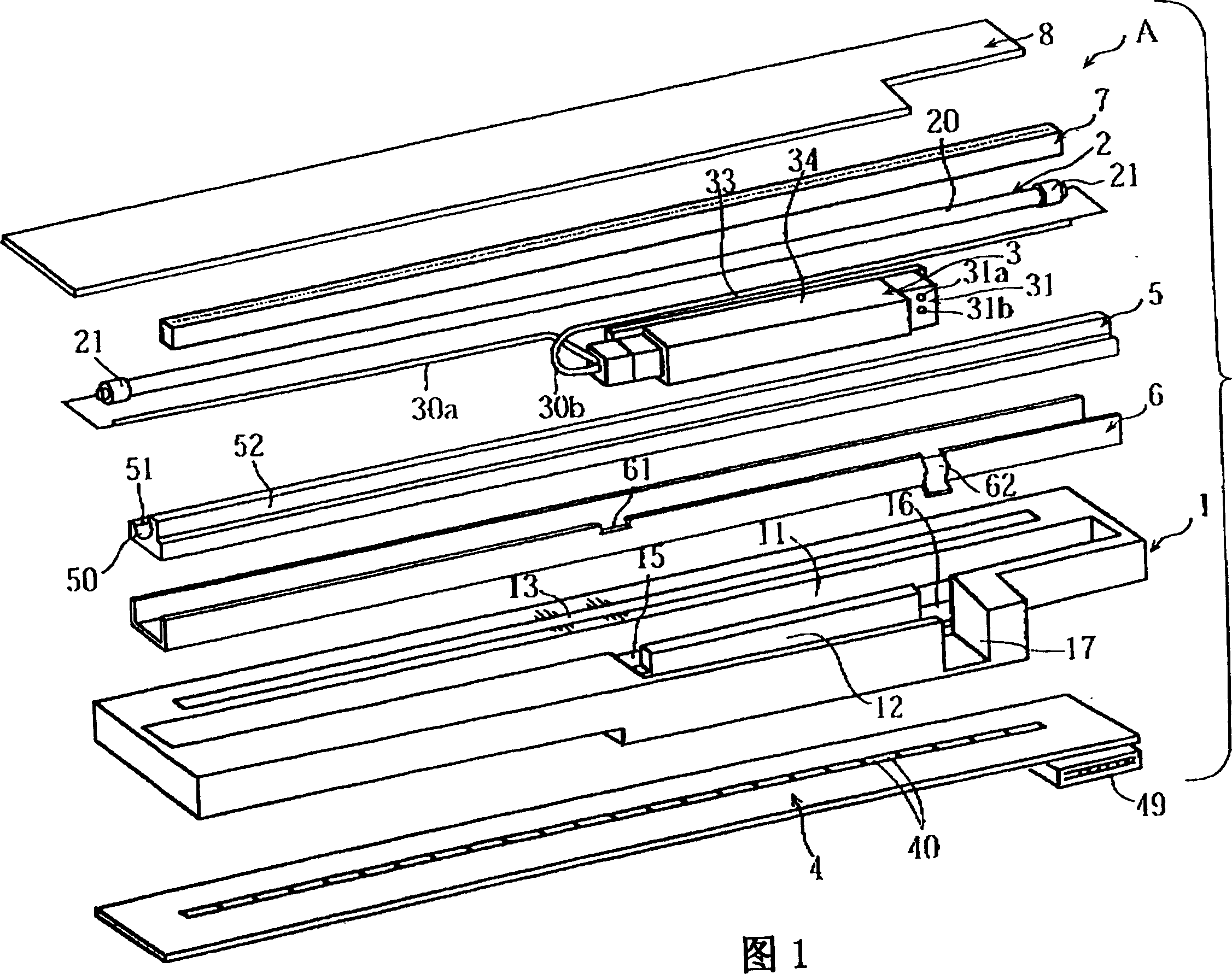
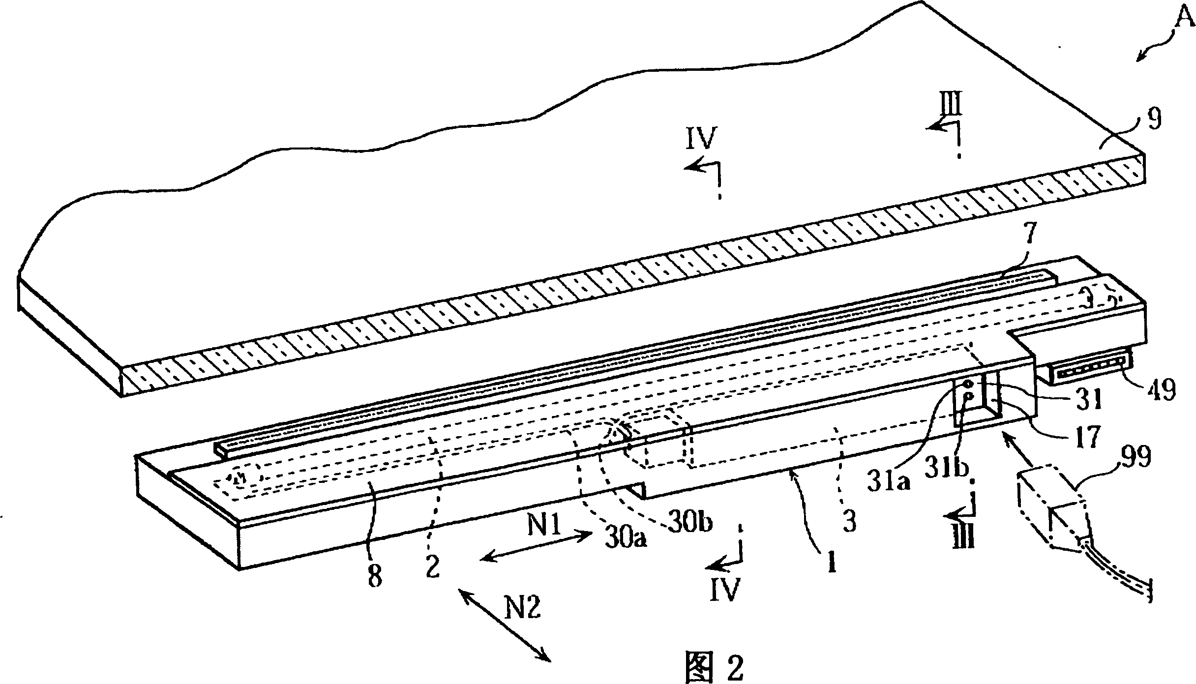
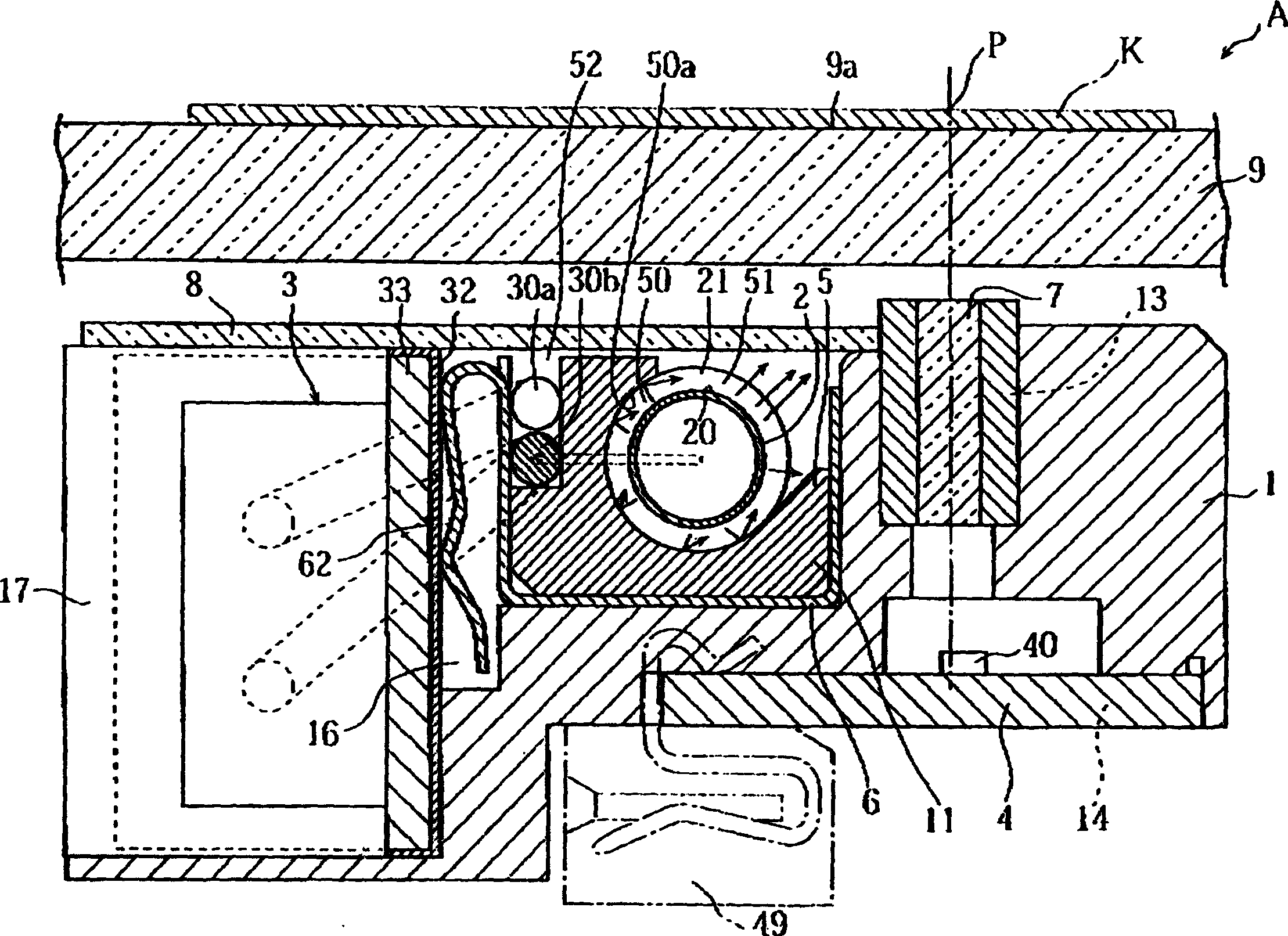
[0056] Referring first to FIG. 1 , it is an exploded schematic diagram of components used in an image reading device according to a first embodiment of the present invention. The image reading device of this embodiment is a flat-panel line image scanner A, which mainly includes a housing 1, a cold cathode tube 2, an inverter 3, a circuit board 4, a light reflection support 5, and a shielding frame 6 , a lens cluster 7 and a transparent cover 8 .

[0057] In the illustrated embodiment, the casing 1 is elongated in one direction (main scanning direction N1 in FIG. 2 ) and has a box structure for accommodating the cold cathode tube 2, the inverter Support 5, shielding frame 6 and lens cluster 7. The housing 1 supports a cover 8 fastened thereon from above. The housing 1 likewise supports a circuit board 4 which is fastened thereto from bel...


PUM


Abstract

An image reading apparatus is provided which includes a cold-cathode tube as a light source for illuminating a document sheet, an inverter for providing the light source with driving power. A connection cable is used for electrically connecting the light source to the inverter. The image reading apparatus also includes three kinds of rows of light receiving elements arranged in the primary scanning direction for detecting the light reflected on the document sheet. A lens array is provided for focusing the reflected light at the respective rows of light receiving elements. The light receiving elements are mounted on a printed circuit board. The light source, the inverter, the lens array and the printed circuit board are supported by a single case of the image reading apparatus.

Description

technical field [0001] The present invention relates to an image reading device, and more particularly, to a line image scanner for optically reading document paper in a full-color manner. The present invention also relates to an image sensing chip most suitable for use in such an image scanner. Background technique [0002] attached Figure 14 A conventional image reading device is shown in . The shown image reading device includes a light source portion Ba composed of a cold cathode tube 1' and a reflection mirror 2'. The conventional device also includes an inverter part Bb for supplying drive energy to the cold cathode tube 1' via a flexible cable 3, and a light guide part Bc provided with reflectors 4a', 4b'. The conventional device also includes an image reading section Bd provided with a lens 5' and an image sensor 6'. [0003] During operation, the light source portion reciprocates in the second scanning direction under the fixed glass plate 7' on which the docume...

Claims


Application Information

Patent Timeline
IPC IPC(8): H04N1/031H04N1/48
CPCH04N1/0315H04N1/0318H04N1/486H04N1/0287H04N2201/03112H04N1/0285H04N1/0312H04N2201/03129H04N2201/03141H04N2201/03145
Inventor 藤本久义大西弘朗高仓敏彦今村典广
Owner ROHM CO LTD
Features
  • R&D
  • Intellectual Property
  • Life Sciences
  • Materials
  • Tech Scout
  • Unparalleled Data Quality
  • Higher Quality Content
  • 60% Fewer Hallucinations
Learn More