Illumination device and liquid crystal display device using the same

a technology of liquid crystal display and illumination device, which is applied in the direction of static indicating device, lighting and heating apparatus, instruments, etc., can solve the problem of low brightness, and achieve the effect of suppressing the drop in display brightness and reducing movement blur

Active Publication Date: 2007-10-02
SHARP KK
View PDF17 Cites 56 Cited by
  • Summary
  • Abstract
  • Description
  • Claims
  • Application Information

AI Technical Summary

Benefits of technology

[0067]An object of the invention is to provide an illumination device which can reduce a movement blur and a tailing phenomenon

Problems solved by technology

Besides, in the sidelight type backlight unit 1000 of the fourth related art described by use of FIG. 76, since a light source, such as the cold cathode

Method used


Image

  • Illumination device and liquid crystal display device using the same
  • Illumination device and liquid crystal display device using the same
  • Illumination device and liquid crystal display device using the same

Examples


first embodiment

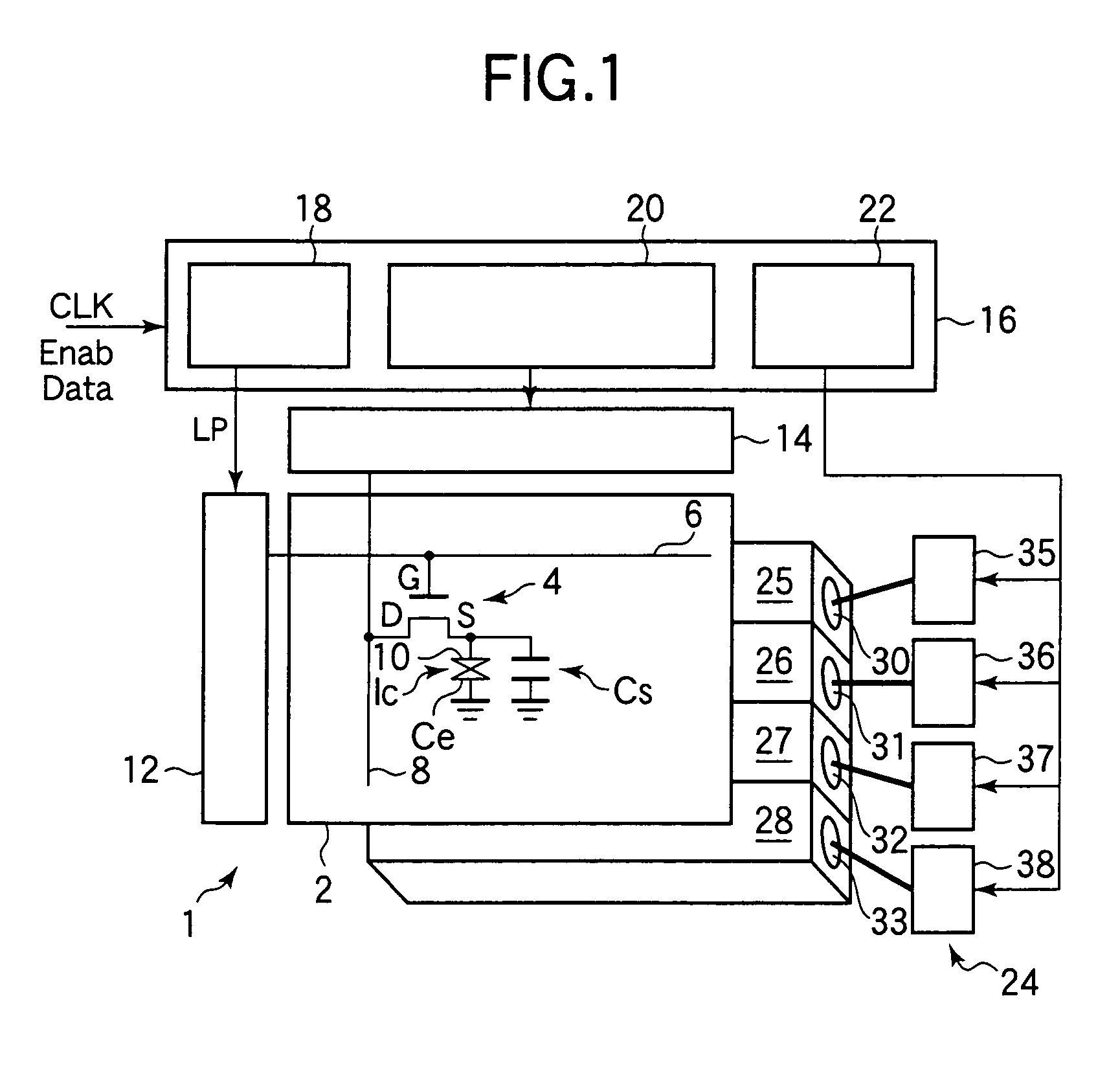
[0155]An illumination device according to a first embodiment of the invention and a liquid crystal display device using the same will be described with reference to FIGS. 1 to 3. First, the rough structure of the illumination device according to this embodiment and the liquid crystal display device using the same will be described with reference to FIG. 1. FIG. 1 shows a schematic state in which a TFT-LCD 1 as an example of the display device is viewed from the side of a panel display surface. In an LCD panel 2, a liquid crystal 1c is sealed between two glass substrates, that is, an array substrate (not shown) on which TFTs 4 are formed and an opposite substrate (not shown) on which common electrodes Ce are formed. In the illustrated LCD panel 2, an equivalent circuit of one pixel is shown. On the array substrate, for example, plural gate bus lines 6 extending in the horizontal direction of the drawing are formed in parallel with each other in the vertical direction. Plural data bus...

second embodiment

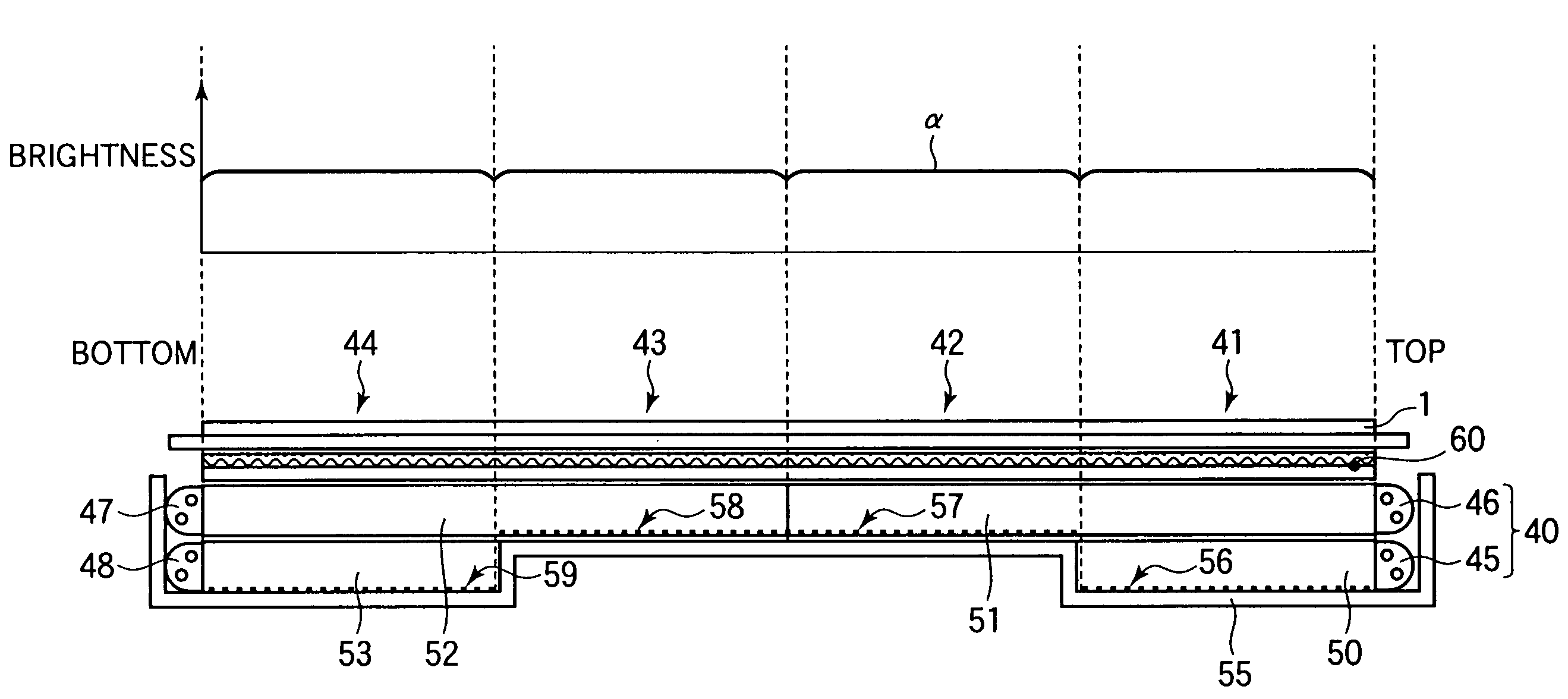
[0195]An illumination device according to a second embodiment of the invention and a liquid crystal display device using the same will be described with reference to FIGS. 4 to 8. First, a rough structure of the illumination device according to this embodiment and the liquid crystal display device using the same will be described with reference to FIGS. 4, 5A and 5B. FIG. 4 shows the rough structure of the illumination device according to this embodiment and the liquid crystal display device using the same. A TFT-LCD 1 shown in FIG. 4 is the same as the TFT-LCD 1 of the first embodiment explained by use of FIG. 1, and structural elements having the same operation and function are denoted by the same symbols, and the description will be omitted. FIG. 5A is a sectional view taken along line A-A of FIG. 4 and shows a section obtained by cutting an illumination device (sidelight type backlight unit) 40, which is used for the TFT-LCD 1 to support the motion picture display according to t...

third embodiment

[0239]An illumination device according to a third embodiment of the invention and a liquid crystal display device using the same will be described with reference to FIGS. 10A to 29 and FIG. 1 showing the first embodiment. This embodiment has been made to solve the problem of the third related art, and realizes a display device in which even if a lighting period of a cold cathode fluorescent lamp of an illumination device is made short, light emission brightness of the cold cathode fluorescent lamp is not required to be raised, and a high quality motion picture image can be obtained.

[0240]Subjective evaluation was performed as to whether or not a difference in picture quality was felt in the case where a ratio (duty rate) of a lighting time of a backlight unit in one frame period was changed, and further, gradation data was processed and transmissivity of liquid crystal was adjusted. It has been found that even if the duty ratio is the same, according to image data, a difference in p...


PUM


Abstract

An illumination device is provided which can reduce a movement blur and a tailing phenomenon on a motion picture display while a drop in display brightness is suppressed, and which can suppress power consumption, can be made small and light, and can prolong the lifetime, and a liquid crystal display device using the same is provided. A light source control part of a control circuit synchronizes a latch pulse signal outputted from a gate driver control part to a gate driver, and outputs light emission control signals to respective light source power supply circuits. The respective light source power supply circuits change emission states of cold cathode fluorescent lamps to one of a first to a third emission states on the basis of the inputted light emission control signals, and illuminate an LCD panel from a rear surface of a display area. A first stage emission state is a non-lighting state, a second stage emission state is a maximum lighting state in which maximum lighting brightness is obtained, and a third emission state is an intermediate lighting state in which brightness of about one half of the second stage emission state is obtained.

Description

BACKGROUND OF THE INVENTION[0001]1. Field of the Invention[0002]The present invention relates to an illumination device for illuminating a display area of a liquid crystal display device, and a liquid crystal display device using the same. Particularly, the invention relates to an illumination device which improves motion picture blur and a tailing phenomenon at the time of display of motion pictures, and a liquid crystal display device using the same.[0003]2. Description of the Related Art[0004][First Related Art][0005]As alternate means of a CRT (Cathode Ray Tube) which is a conventional typical display device, in recent years, an active matrix type liquid crystal display device (hereinafter abbreviated to TFT-LCD) in which a TFT (Thin Film Transistor) or the like is provided as a switching element at each pixel has gone mainstream.[0006]In principle, in the TFT-LCD, gradation data written into each pixel is held for one frame period (equal to a period of a vertical synchronizatio...

Claims


Application Information

Patent Timeline
IPC IPC(8): G09G3/36G02F1/133G02F1/13357G09G3/34G09G5/10
CPCG02F1/1336G09G3/342G09G3/3611G09G3/3648G02B6/0076G02B6/0046G09G2360/16G02B6/0078G09G3/3666G09G5/10G09G2310/024G09G2310/0245G09G2310/061G09G2320/0233G09G2320/0261G09G2320/064G09G2320/0646G02F1/133
Inventor KOBAYASHI, TETSUYASUZUKI, TOSHIHIROSUGAWARA, MARIHAMADA, TETSUYAHAYASHI, KEIJIYAMADA, FUMIAKIFURUKOSHI, YASUTAKENISHIDO, MASANORI
Owner SHARP KK
Why Eureka
Try Eureka