Optical-sheet supporting structure, lighting device and display device

a technology of supporting structure and optical sheet, which is applied in the direction of optics, lighting and heating equipment, instruments, etc., can solve the problems of not being able to uniformly radiate light from the light source, and achieve the effect of preventing vaulting, ensuring stability, and improving the quality of lighting devices

Inactive Publication Date: 2009-10-29
SHARP KK
View PDF6 Cites 57 Cited by
  • Summary
  • Abstract
  • Description
  • Claims
  • Application Information

AI Technical Summary

Benefits of technology

[0014]A posture retaining portion preferably is provided, and is disposed on one of the base-side panel support and the facing portion, and abuts on the other so as to provide two-point support for the facing portion together with the holding protrusion. Thereby, the facing portion can be prevented from leaning inward, and therefore the distal end of the facing portion can be prevented from interfering with the optical sheet.
[0015]An optical-sheet supporting structure according to a preferred embodiment of the present invention includes a flat panel, an optical sheet placed on the panel so that an exposed portion is left on the periphery thereof, a base-side panel support that abuts on the periphery of the panel so as to hold the panel, and a holding-side panel support which is disposed on the opposite side of the base-side panel support and includes a facing portion positioned so as to hold the periphery of the panel and the optical sheet in cooperation with the base-side panel support and therebetween. The holding-side panel support preferably has a frame-like shape as a whole. Further included are at least two posture retaining portions arranged to retain the posture of the facing portion so that the facing portion extends along the surface of the optical sheet. According to this construction, two-or-more-point support for the facing portion is provided, and thereby firm support can be achieved.
[0016]According to a preferred embodiment of the present invention, other components can be prevented from applying intense pressure on the optical sheet. Therefore, the optical sheet can be prevented from vaulting, even when ambient temperature or the like changes. Thereby light from the light source can be radiated uniformly, which contributes to quality improvement of a lighting device.

Problems solved by technology

This could result in failing to uniformly radiate light from the light source to the liquid-crystal panel.

Method used


Image

  • Optical-sheet supporting structure, lighting device and display device
  • Optical-sheet supporting structure, lighting device and display device
  • Optical-sheet supporting structure, lighting device and display device

Examples


first preferred embodiment

[0028]A first preferred embodiment according to the present invention will be explained with reference to FIGS. 1 through 4.

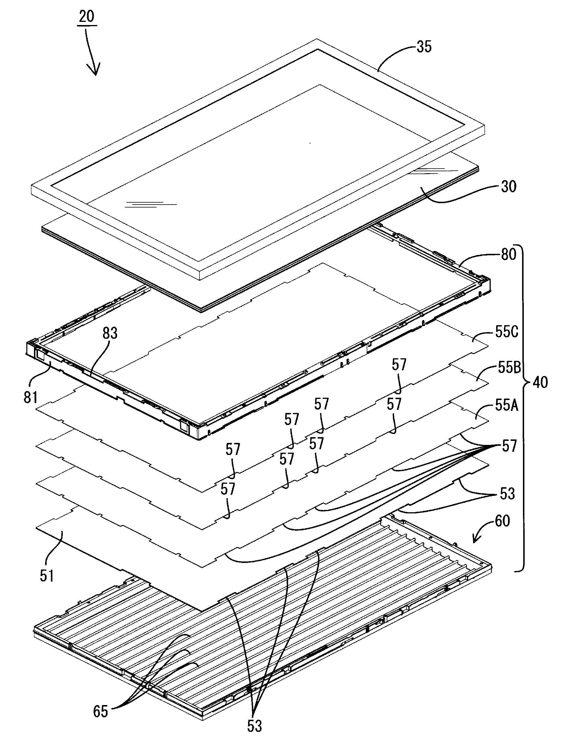
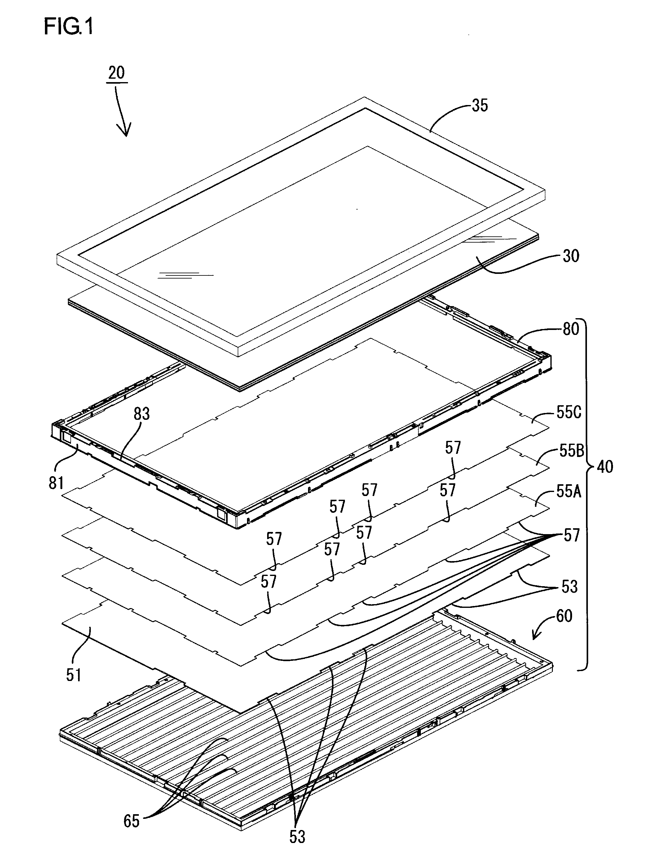
[0029]FIG. 1 is an exploded perspective view of a display device 20. The display device 20 preferably includes a liquid crystal panel 30 having a planar surface capable of image display, and a backlight device (corresponding to a lighting device of a preferred embodiment of the present invention) 40. The liquid-crystal panel 30 includes a pair of glass substrates, liquid crystal filled between the glass substrates, and a pair of polarizing plates applied to the outer surfaces of the respective glass substrates. It is placed on a backlight device 40 with an overlap, and held by a substantially rectangular-shaped outer frame 35.

[0030]The backlight device 40 preferably is a so-called direct-light-type backlight device, in which a plurality of cold-cathode tubes 65 positioned beneath the liquid-crystal panel 30 are arranged in a row sideways. A base tray 60 that co...

second preferred embodiment

[0048]Next, a second preferred embodiment of the present invention will be explained with reference to FIG. 5.

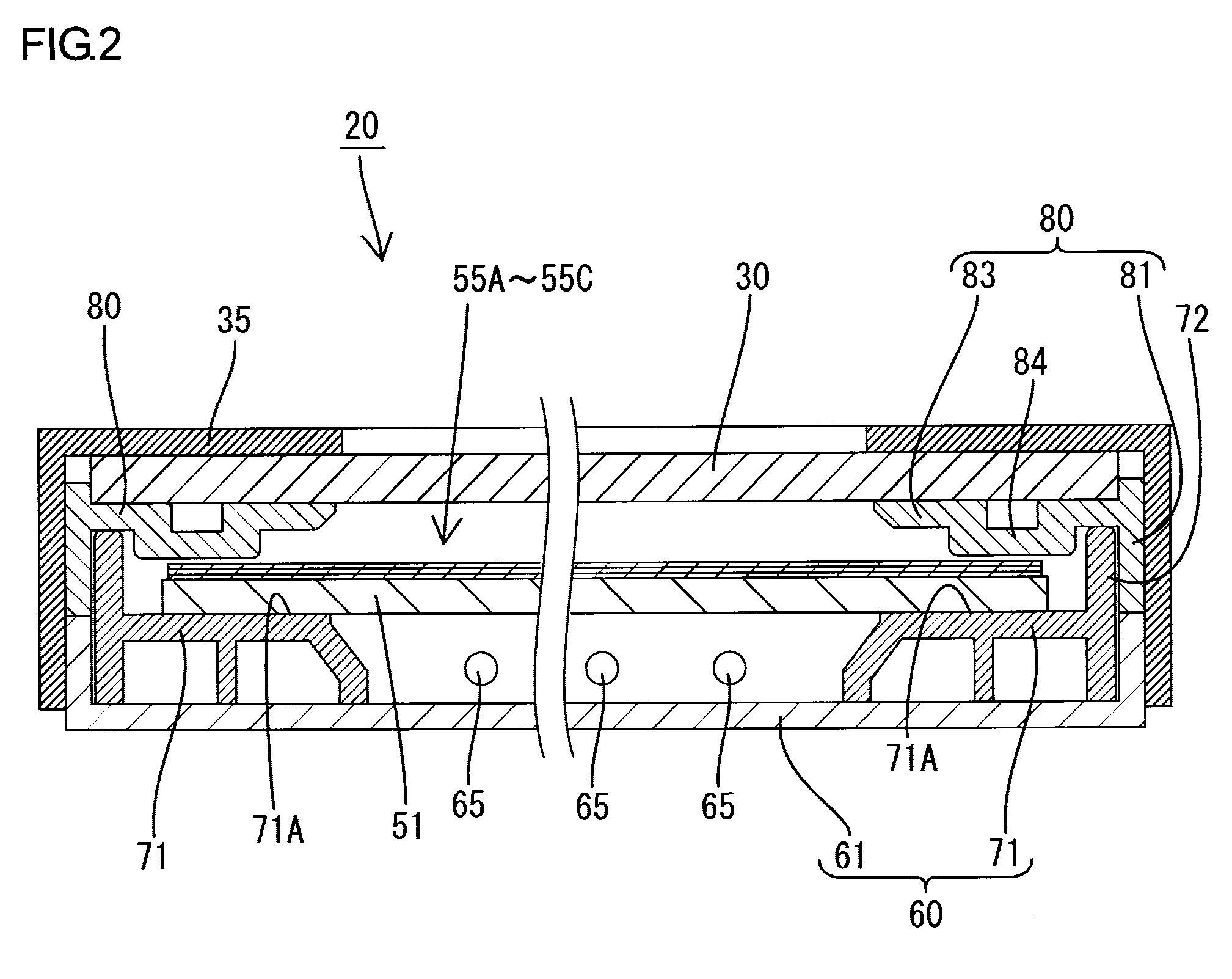
[0049]In the first preferred embodiment, the holding protrusion 85 is provided on the lower surface of the holding base 84 so that its end surface abuts on the exposed portion 54 of the diffuser plate 51. Conversely, in the second preferred embodiment, a holding protrusion 95 is arranged on a diffuser plate 90 so that its end surface abuts on the lower surface 84A of a holding base 84. According to this construction, operation and effects similar to those of the first preferred embodiment can be achieved. In FIG. 5, the same components as the first preferred embodiment are designated by the same symbols, and redundant explanation is omitted.

third preferred embodiment

[0050]Next, a third preferred embodiment of the present invention will be explained with reference to FIG. 6.

[0051]In the first preferred embodiment, two-point support for the facing portion 83 is provided by the raised portion 72 and the holding protrusion 85. In the third preferred embodiment, instead of the holding protrusion 85, a posture retaining protrusion (corresponding to a posture retaining portion of the present invention) 100 is additionally provided on the base member 71, so that two-point support for the facing portion 83 is provided by the posture retaining protrusion 100 and the raised portion 72 both abutting on the lower surface of the facing portion 83. The other constructions are similar to the first preferred embodiment.

Other Preferred Embodiments

[0052]The present invention is not limited to the preferred embodiments described above with reference to the drawings. The following preferred embodiments are included in the technical scope of the present invention, f...


PUM

PropertyMeasurementUnit
thicknessaaaaaaaaaa
temperatureaaaaaaaaaa
pressureaaaaaaaaaa

Abstract

In a backlight device, a diffuser plate and a plurality of optical sheets are disposed above a base tray that includes a plurality of cold-cathode tubes therein. The diffuser plate is sandwiched in between a base member, which holds the bottom surface thereof, and a facing portion of an inner frame disposed on the top surface side thereof. A holding protrusion is arranged on the facing portion so as to abut on an exposed portion located on the periphery of the diffuser plate. According to this construction, even when the backlight device is used in an upright orientation, the diffuser plate can be prevented from leaning forward, and thereby pressure applied on the optical sheets can be prevented.

Description

BACKGROUND OF THE INVENTION[0001]1. Field of the Invention[0002]The present invention relates to an optical-sheet supporting structure, a lighting device and a display device.[0003]2. Description of the Related Art[0004]A backlight device used for a liquid-crystal display device or the like is widely known, and includes an optical component having a plurality of optical sheets stacked on a panel, such as a diffuser plate or a light guide plate (as described in JP-A-2002-341345, for example). The optical component is disposed on the front or side of a light source in order that light from the light source may be uniformly radiated to a liquid-crystal panel. A structure shown in FIG. 7 is provided as an example of its supporting structure, which supports a panel 10 and optical sheets 11 by sandwiching in the periphery thereof between a base member 15 and a holding member 16. According to this supporting structure, assembly can be readily achieved by simply laying the parts on top of o...

Claims


Application Information

Patent Timeline
Patent Type & Authority Applications(United States)
IPC IPC(8): G02F1/1333F21V17/06F21V17/00
CPCG02F1/133608G02F2201/54G02F2001/133317G02F1/133317
Inventor HISADA, YASUNARI
Owner SHARP KK
Why Eureka
Try Eureka