Metallization of carbon nanotubes for field emission applications

a carbon nanotube and field emission technology, applied in the manufacture of electric discharge tubes/lamps, electrode systems, liquid/solution decomposition chemical coatings, etc., can solve the problems of difficult to achieve uniformity, limited substrates that can be used, and poor field emission quality of mwnts compared to single-wall carbon nanotubes

Inactive Publication Date: 2004-01-29
NANO
View PDF1 Cites 56 Cited by
  • Summary
  • Abstract
  • Description
  • Claims
  • Application Information

AI Technical Summary

Problems solved by technology

However, this has several draw-backs.
However, MWNTs have poorer field emission quality compared to single-wall carbon nanotubes (SWNTs).
The substrate is subjected to high temperature, typically above 600.degree. C., limiting the substrates that can be used.
Uniformity is difficult to achieve because of the high temperature growth processes required.
As a result, the manufacture of cathodes using this process will be very expensive due to the number and complexity of post-processing steps needed to generate a material capable of producing the desired level of field emission.
Third, uniform deposition over large area substrates is far more feasable using currently-available, low-cost equipment.
Current dispensing processes, however, have their disadvantages.
These factors limit the performance of the CNT material.
These "activation" process steps, however, can add cost to the product and may lead to non-uniform performance.
Yet another disadvantage of current dispensing techniques is that the dispensed CNT fibers may not have sufficiently good contact to the substrate or the substrate's conductive layer such that this impedes their ability to supply the electrons needed for field emission.
This method has the inherent aforementioned disadvantages of growing CNTs on the substrate.
Furthermore, were the CNT fibers to be dispensed onto the substrate and then coated, the problems of separating the CNT fibers for improved emission would still remain.

Method used


Image

  • Metallization of carbon nanotubes for field emission applications
  • Metallization of carbon nanotubes for field emission applications
  • Metallization of carbon nanotubes for field emission applications

Examples


example 1

[0030] Coating Single-Wall Carbon Nanotubes with a Cobalt Thin Film

[0031] This process provides a way of depositing a metal thin film or coating on the surface of carbon nanotubes using an electroless plating technique. Using this relatively inexpensive and simple process, metallized carbon nanotubes can be made efficiently in relatively large amounts.

[0032] The single-wall carbon nanotube (SWNT) material used here was purchased from Iljin Nanotech, Inc. (Korea). The length of the SWNTs ranged from approximately several micrometers to approximately 20 micrometers, and the diameters were generally less than about 2 nanometers.

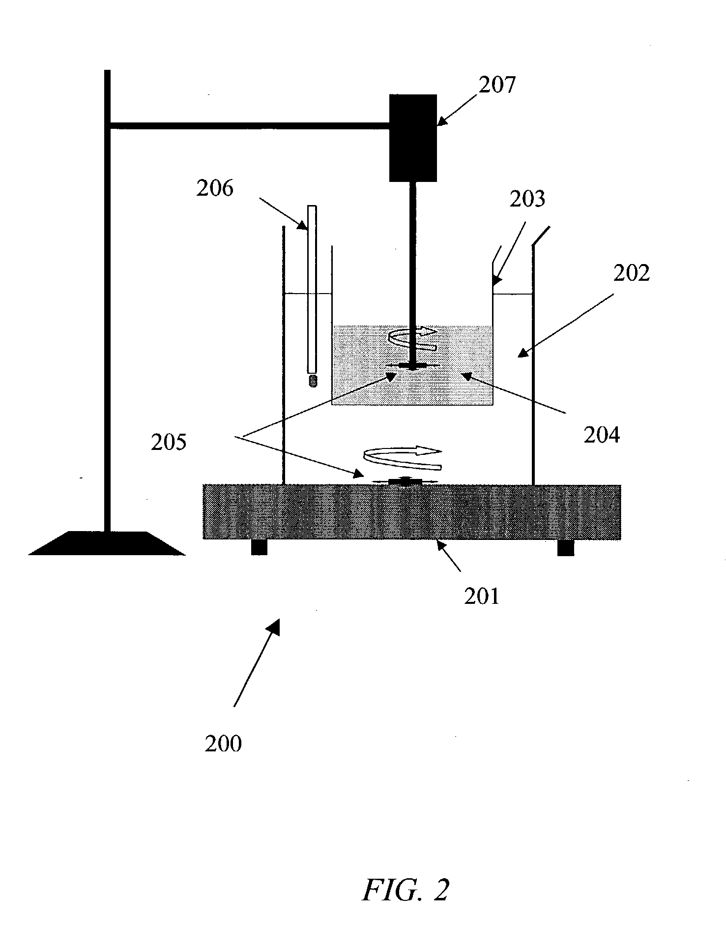
[0033] Referring to FIG. 2, electroless plating apparatus 200 comprises an electroless plating solution 204 contained in a beaker 203 which in turn is immersed in a water bath 202. Water bath 202 is heated by a magnetic stirring hotplate 201 and temperature is monitored by thermometer 206. Stirring is accomplished with stir bars 205 activated by the magnetic sti...

example 2

[0043] Dispensing Carbon Nanotubes onto a Substrate

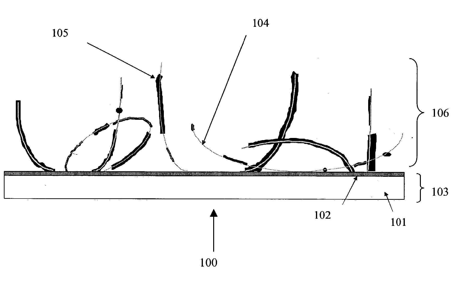
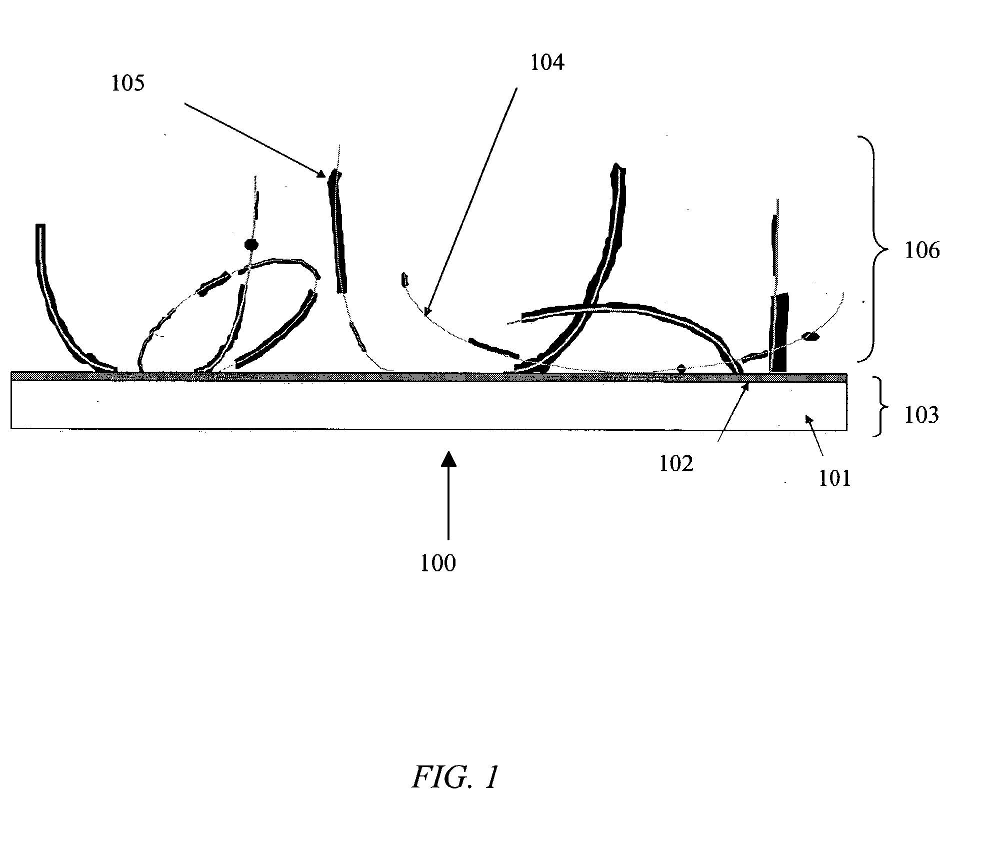
[0044] In this example, cobalt-metallized SWNT powder was mixed with isopropyl alcohol (IPA) to form a suspension. The suspension comprised approximately 1 gram of metallized SWNTs in 1000 ml IPA. Because the SWNTs clump together readily, ultrasonic agitation was used to disperse the nanotubes in the IPA before spraying the solution onto cathode substrates. The SWNT / IPA suspension was sprayed onto conductive indium-tin-oxide (ITO) / glass substrate with an area of 2.times.2 cm.sup.2. In order to prevent the IPA from flowing uncontrollably, the substrate was heated up to approximately 30-70.degree. C. on both the front side and back side during the spraying process. The substrate was sprayed back and forth several to tens of times until the carbon nanotubes covered on the entire surface. The thickness of the carbon nanotube layer was about 1-20 .mu.m. The film was then dried in air.

[0045] FIGS. 3 and 4 show optical images of CNT materi...


PUM

PropertyMeasurementUnit
thicknessaaaaaaaaaa
thicknessaaaaaaaaaa
temperatureaaaaaaaaaa

Abstract

The present invention is directed towards metallized carbon nanotubes, methods for making metallized carbon nanotubes using an electroless plating technique, methods for dispensing metallized carbon nanotubes onto a substrate. The present invention is also directed towards cold cathode field emitting materials comprising metallized carbon nanotubes, and methods of using metallized carbon nanotubes as cold cathode field emitters.

Description

[0001] The present application claims priority to the following U.S. Provisional Patent Application, Serial No. 60 / 417,246.[0002] The present invention relates in general to nanostructured materials, and in particular, to using modified carbon nanotubes for field emission applications.BACKGROUND INFORMATION[0003] Carbon nanotubes (CNTs) are currently being investigated for use as cold electron sources in a variety of applications. These include displays, microwave sources, x-ray tubes, etc. For CNTs to be used as a cold cathode, they must be placed on a conductive surface (conductive substrate or conductive film on a non-conductive substrate). This has led some to place catalysts on the substrate surface and grow the carbon nanotubes in situ using CVD techniques (Kim et al., J. Appl. Phys., 90(5), 2591 (2001)). However, this has several draw-backs. This technique typically grows multi-wall carbon nanotubes (MWNTs). However, MWNTs have poorer field emission quality compared to single...

Claims


Application Information

Patent Timeline
Patent Type & Authority Applications(United States)
IPC IPC(8): C23C18/16H01J9/02
CPCB82Y10/00B82Y30/00C23C18/1204C23C18/1635Y10T428/12007C23C18/31H01J9/025H01J2201/30469C23C18/2066
Inventor MAO, DONGSHENG
Owner NANO
Why Eureka
Try Eureka