

Transparent Conductive Carbon Nanotube Film and a Method for Producing the Same
a carbon nanotube film, transparent technology, applied in the direction of conductive layers on insulating supports, liquid/solution decomposition chemical coating, superimposed coating process, etc., can solve the problems of no good conductivity and no resin film conductive material of high transparency
- Summary
- Abstract
- Description
- Claims
- Application Information
AI Technical Summary
Benefits of technology
Problems solved by technology
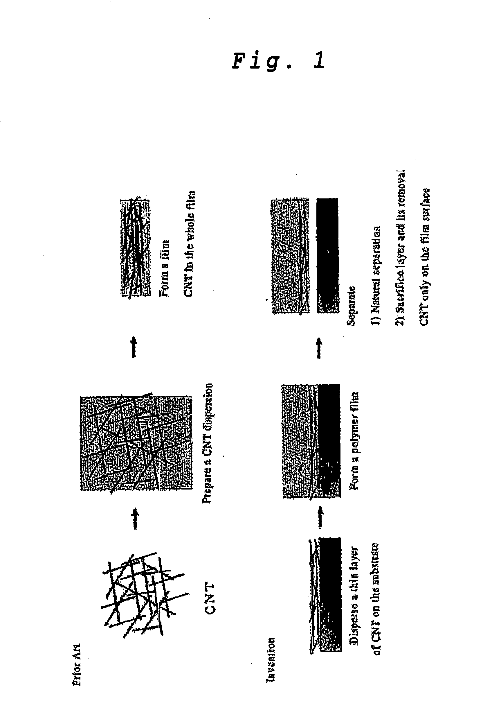
Method used
Image

Examples
example 1
[0077] A transparent conductive carbon nanotube film was formed by employing the following conditions and process:
[0078] Step (A):
[0079] Substrate:
[0080] A silicon substrate having a SiO2 film with a thickness of 600 nanometers was used as the substrate (measuring 2 cm by 6 cm at maximum).
[0081] Method of Dispersing CNT:
[0082] Carbon nanotubes were directly synthesized on the silicon oxide substrate by a method of chemical vapor-phase synthesis. More specifically, an iron particle catalyst was first synthesized on the silicon oxide substrate by the method of H. Dai et al. (H. Dai, et al., Nano Letters Vol. 3, p. 157 (2003)). Then, the silicon oxide substrate having the iron particle catalyst fixed thereon was placed in a chemical vapor-phase reactor having a diameter of 1 inch and while it was heated to 750 degrees in an argon and hydrogen atmosphere, carbon nanotubes were grown on the substrate for 1 to 2 minutes, while ethylene gas was used as a carbon source. This method can...
example 2
[0100] Conductive carbon nanotube films were manufactured by using various kinds of resins by the same method as in Example 1.
[0101]FIG. 7 shows the appearance of the conductive films as obtained. The symbols in the figure mean:
[0102] PS: polystyrene
[0103] PDMS: polydimethylsiloxane
[0104] PVC: polyvinyl chloride
[0106] PMMA: polymethyl methacrylate
[0107] ZELATIN: gelatin
[0109] The conditions under which the above conductive PVC film was formed are shown below by way of example.
[0110] Di-2-ethylhexyl phthalate (also called dioctyl phthalate, Di-2-ethylhexyl phthalate, C6H4(COOC8H17)2, Kanto Chemical Co., Inc., 99.5%) was added 10-20% by weight as a plasticizer to a PVC powder (Aldrich, Mw=43,000), followed by the addition of cyclohexanone (Cyclohexanone, C6H10O, Wako Pure Chemical Industries, Ltd., 99.0%) about 2-4 times the volume. They were stirred for 12-24 hours by a magnetic stirrer to form a uniform solution.
[0111] A...
example 3
[0120] The SWCNT-PVC film according to Case No. 2-3 in Example 2 was examined for its flexibility and any change caused to its surface resistance by flexing by the flexing (bending) test as shown in FIG. 11.
[0121] A 20 mm square conductive carbon nanotube film was employed for the test. The film formed from the resin and having a thickness of 10 to 50 μm (usually 30 to 40 μm) was employed as a test specimen. The film was coated at both ends with an electrically conductive paste (product of Chemtronics) having a width of about 2 mm and defining an electrode. The film was curved with its single-walled carbon nanotube layer facing outwards was placed between clamps and was fixed with a double-sided adhesive tape. Finally, the electrodes at both ends of the film were connected to both terminals of a resistance meter. A gold or copper wire (0.2 mm in diameter) and the conductive paste mentioned above were used for their connection.
[0122] The flexing test was conducted by tightening the...
PUM
| Property | Measurement | Unit |
|---|---|---|
| Fraction | aaaaa | aaaaa |
| Electrical resistance | aaaaa | aaaaa |
| Electrical resistance | aaaaa | aaaaa |
Abstract
Description
Claims
Application Information