
LED sensor night light

Inactive Publication Date: 2006-01-12
YUEN SE KIT
View PDF3 Cites 56 Cited by
  • Summary
  • Abstract
  • Description
  • Claims
  • Application Information

AI Technical Summary

Benefits of technology

[0009] A main object of the present invention is to provide a LED sensor night light having an ability to focus all angles of lights in form of an optical sphere emitting a more powerful light with the same amount of power supply.
[0010] Another object of the present invention is to provide a LED sensor night light which is environmental friendly with a long life span.
[0012] Another object of the present invention is to provide a LED sensor night light with a mean of automate mechanism which allows night light to turn on and on automatically as needed.

Problems solved by technology

One disadvantage for most convention night lights is that many night lights use incandescent or fluorescent bulbs with relatively short life spans.
It is not environmental friendly at all.
Yet, it ultimately becomes costly for both the earth and the consumers.
Another disadvantage is that most conventional night lights provide only one position of illumination, normally at an outer surface but not at the surface which is against the wall outlet.
Another disadvantage is that most conventional night lights use incandescent or fluorescent bulbs which become very hot at its surface after an extended period time of usage.
Elderly seniors and children might accidental have contact with those bulbs and result injuries.
Another disadvantage is that most conventional night lights do not provide any means of automates mechanism which allows night light to turn on and off automatically as needed.

Method used


Image

  • LED sensor night light
  • LED sensor night light
  • LED sensor night light

Examples


Embodiment Construction

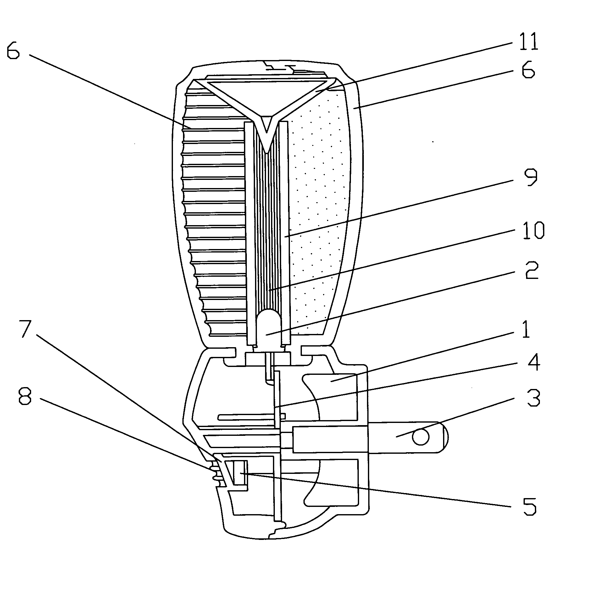
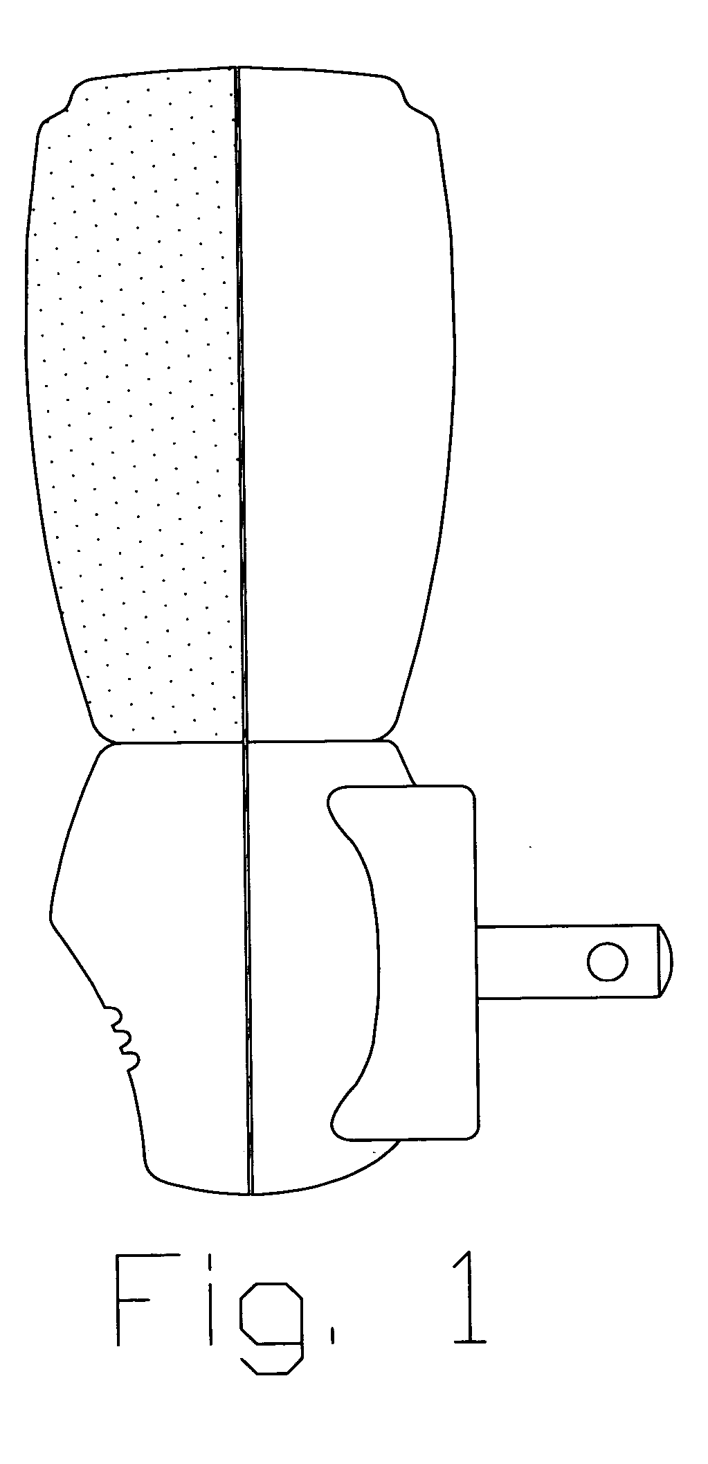
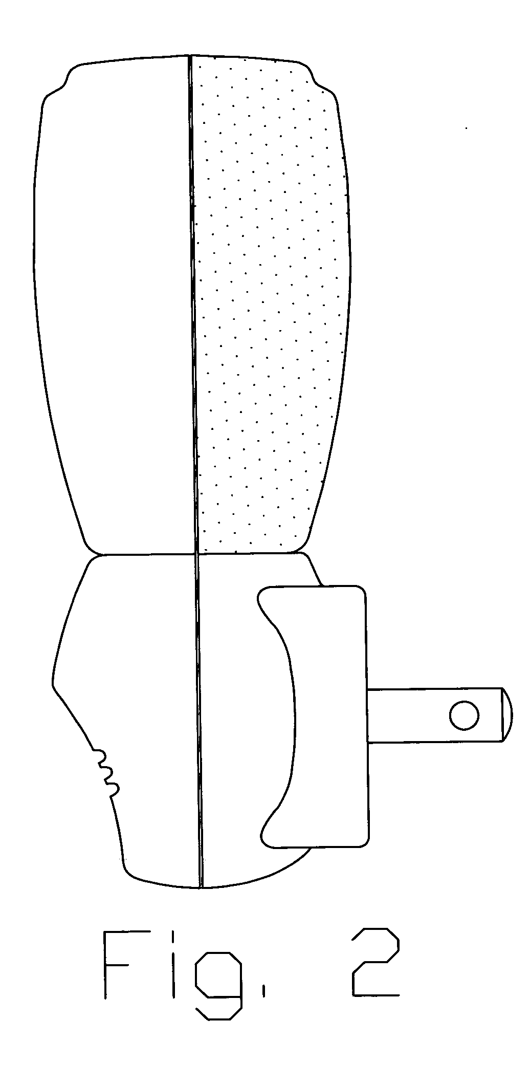
[0031] The present invention comprises of an illuminant (1) which is usually a cylinder-shaped structure. Inside the illuminant, there are at least one cold-cathode super-light source (2) and two metal power plugs (3). Said metal power plugs (3) are fastened to a circuit board (4) on one side. Said circuit board (4) further comprise of at least one sensor circuitry (5), in front of said circuit board (4) there is a transparent front protective shade and a semi-transparent back protective shade (7), which is closely mounted to a transmitting hole (8) in the front of said illuminant (1). Said metal power plugs (3) are plugged into a power socket to obtain power for said circuit board (4) of said illuminant (1). At daytime, natural light goes through said transmitting hole (8) of said illuminant (1) to reach said sensor circuitry (5), which then turns off said cold-cathode light source (2) automatically. In another word, at night, said sensor circuitry (5) senses no natural light, and ...


PUM


Abstract

A LED sensor night light comprises a housing consists of a front panel and a back panel, a transparent front protective shade with refractive angels at its surface; and a semi transparent back protective shade, and at least one cold-cathode light source as a illuminant is affixed in between said front panel and said back panel, and a plurality of circuit boards with at least one sensor circuitry, at least one fluorescent optic integrating pillar is attached in the center portion of said circuit board and placed to cover said light source, and a plurality of metal power plug, and at least one light-reflecting mirror in an arch shape with multiple reflecting angels which provide a night light night light with two positions of illumination, a mean of automate mechanism which allows night light to turn on and on automatically as needed and mean of balancing and converging said cold-cathode light source into a light sphere to relatively increase a lighting power with the same given power supply and light source.

Description

BACKGROUND OF THE PRESENT INVENTION [0001] 1. Field of Invention [0002] The present invention is relates to a night light and more particularly to a LED sensor night light. [0003] 2. Description of Related Arts [0004] Conventional night lights generally providing two types light emitting, i.e. scatted, and diffused pattern of light or a narrow beam of light. People use a night light that emits a narrow beam when illuminate a relatively small surface directly in front of a lens such as a wall or step. Meanwhile, when use in a large area such as hallway, bedroom and restroom, a night light that emits a scattered, diffused pattern light will be employed. [0005] One disadvantage for most convention night lights is that many night lights use incandescent or fluorescent bulbs with relatively short life spans. Some manufacturers take advantage of a relatively short life span of bulbs by marketing night lights with non-replaceable bulbs so that the entire night light must be replaced as soo...

Claims


Application Information

Patent Timeline
IPC IPC(8): H01R33/00F21SF21S8/00F21V7/00F21V23/04H01R13/717
CPCF21S8/035F21V7/0008F21V23/0442H01R2103/00H01R13/7175H01R24/68F21Y2101/02F21Y2115/10
Inventor YUEN, SE KIT
Owner YUEN SE KIT
Learn More