Cooling apparatus and method

a cooling apparatus and cooling technology, applied in the direction of cooling/ventilation/heating modification, semiconductor/solid-state device details, semiconductor devices, etc., can solve the problem of difficult dissipation of heat generated in such a miniaturized version, and achieve the effect of small thickness dimension

Inactive Publication Date: 2007-08-07
SALMON TECH
View PDF14 Cites 39 Cited by
  • Summary
  • Abstract
  • Description
  • Claims
  • Application Information

AI Technical Summary

Benefits of technology

[0009]The Micro Blade embodiment described herein is designed to use the same integrated circuit (IC) chips as the system it replaces. Consequently, it must dissipate the same amount of power, 480 watts in the case of the HS40 server example. In the preferred embodiment, this is achieved using a folded system-in-package (SIP) built on a copper foil substrate; copper comprises approximately 78% of the SIP volume, providing good heat transfer characteristics for cooling. By wrapping the SIP in a hermetic copper jacket it becomes a Micro Blade; a miniaturized stand-alone unit that can be connected to outside elements using a cable. It is mechanically rugged and also thermally rugged; “thermally rugged” means that it can effectively distribute localized hot spots and can also withstand brief surges in overall heat generation. It is preferably cooled in water or other liquid coolant, although air cooling is also a viable option by adding finned elements and forced air, as is known in the art. Yet another option is to provide heat pipes that carry heat produced in the copper jackets to remote radiators where it is dissipated using large area surfaces.

Problems solved by technology

However, dissipating the heat generated in such a miniaturized version is difficult.

Method used


Image

  • Cooling apparatus and method
  • Cooling apparatus and method
  • Cooling apparatus and method

Examples


Embodiment Construction

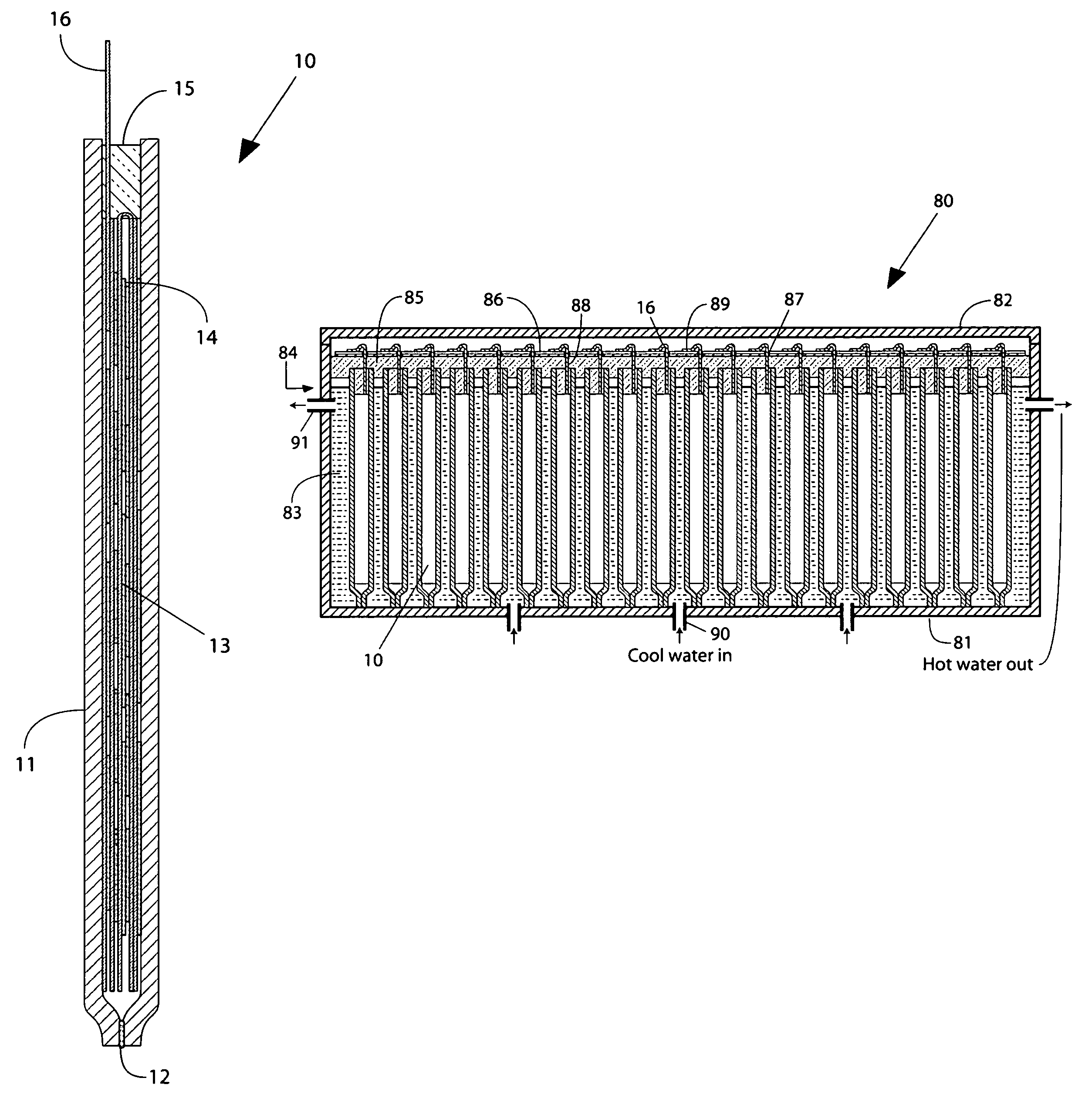
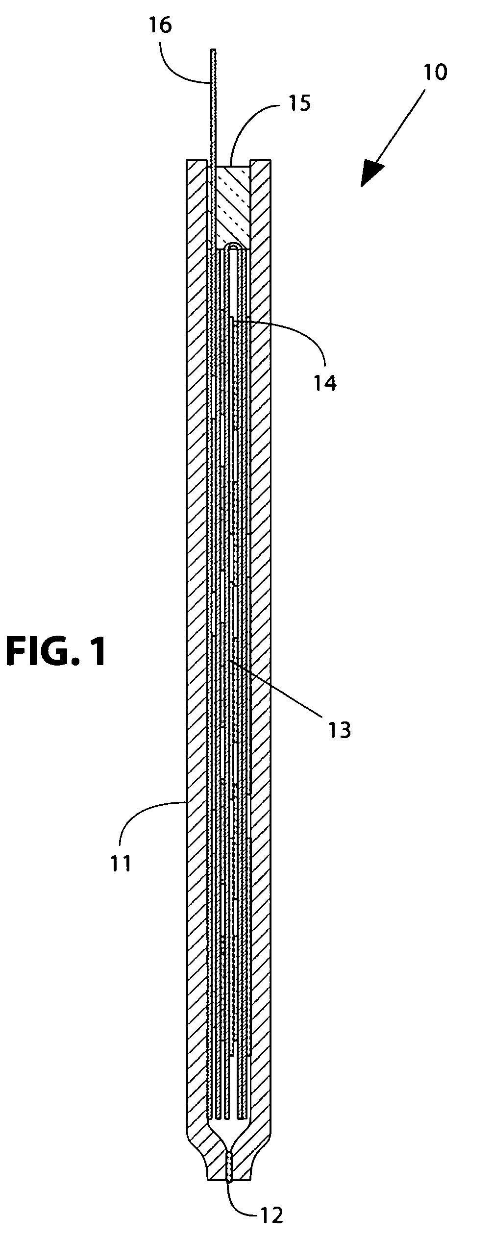
[0021]The cross-section of FIG. 1 illustrates Micro Blade 10 of the current invention, at a scale of approximately 4×. Micro Blade 10 can be of any size, but preferably has a thin form factor for ease of cooling the active circuits inside. Copper jacket 11 is soldered, welded, or brazed at crimped edges 12 to form a hermetic package. Inside the copper jacket is an electronic assembly that is preferably a folded system in package (SIP) 13 including IC chips 14. At the top of Micro Blade 10 is a semi-hermetic seal 15 that also provides a strain relief for cable 16. Semi-hermetic seal 15 may be formed using an epoxy adhesive or a potting compound, as is known in the art. Cable 16 connects to electronic assembly 13 using a direct attachment (like flip chip), as will be further described. Cable 16 also includes a section that is hermetic, as will be further described.

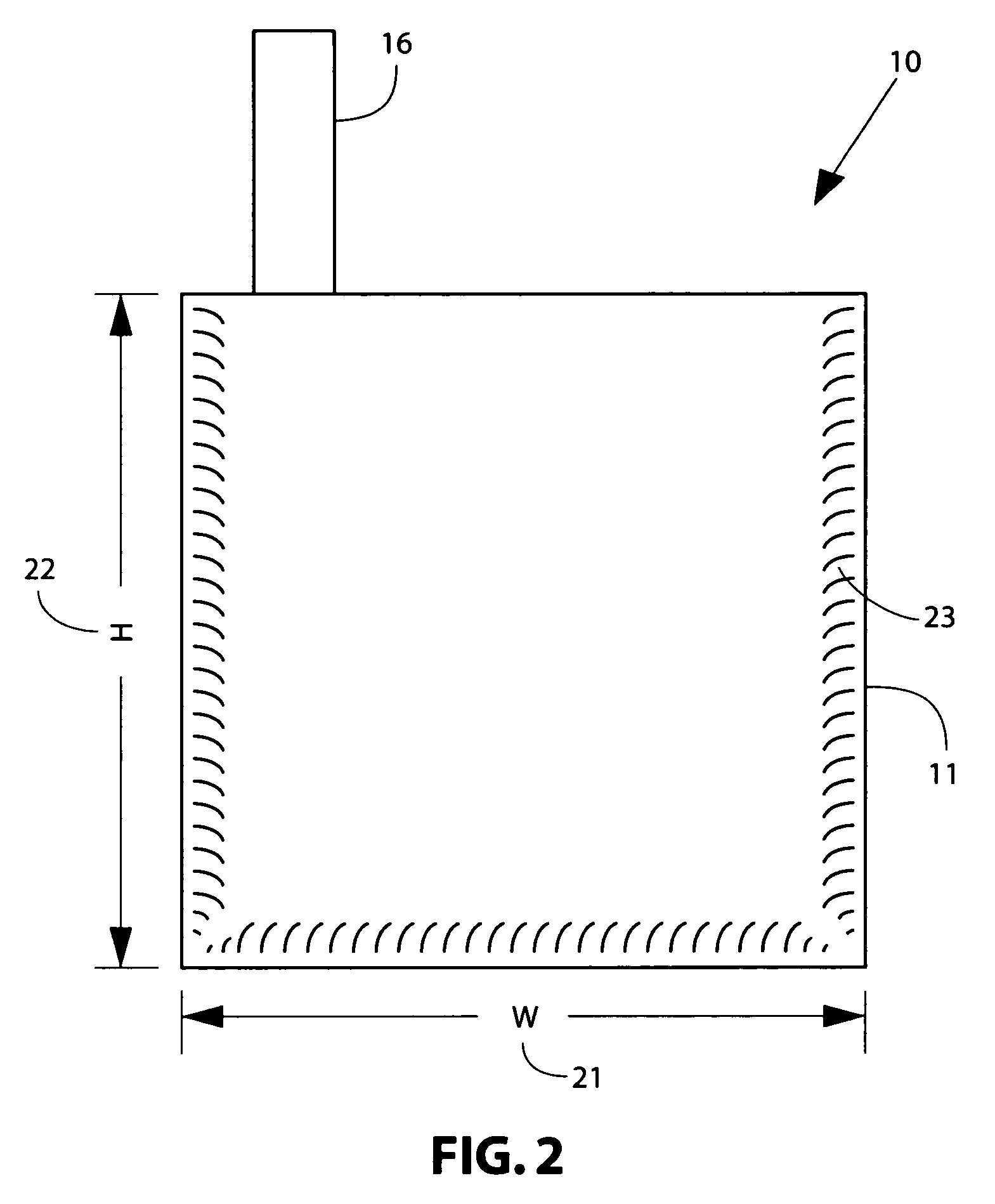
[0022]FIG. 2 is a side view of Micro Blade 10, showing cable 16. Cable 16 typically carries power and high speed signals, ...


PUM


Abstract

A Micro Blade is described for implementing an electronic assembly having a thin profile; it is a miniaturized stand-alone unit that is mechanically and thermally rugged, and connects to external components using a cable. The electronic assembly is preferably fabricated on a copper foil substrate including an interconnection circuit, a special assembly layer, and directly attached components. The components are preferably in bare die form, and are preferably attached using plated copper spring elements inserted into wells filled with solder. The copper foil substrate may be folded to form a compact system in package (SIP) inside of the Micro Blade. A jacket comprised of thermally conductive members is formed around the electronic assembly using hermetic seams. The Micro Blade is preferably cooled by immersion in water contained in a tank; the water is cooled and circulated using an external pumping system.

Description

RELATED APPLICATIONS[0001]This application claims priority to Provisional Application Ser. No. 60 / 570,199 filed May 11, 2004.THE INVENTION[0002]This invention relates to cooling of electronic components and systems, and more particularly to a thermal architecture for liquid cooling of electronic sub-assemblies connected to a motherboard or backplane.BACKGROUND OF THE INVENTION[0003]Blade components have a characteristic form factor; they have a thickness dimension substantially smaller that their height and width. This provides a convenient packaging arrangement for a large system, wherein multiple blades can be inserted in slots in a chassis, each blade providing a standalone capability, and each blade replaceable if problems develop.[0004]Advanced packaging technology may be applied to reduce the dimensions of such a blade assembly. However, dissipating the heat generated in such a miniaturized version is difficult. It is helpful to make the blade as thin as possible. This provide...

Claims


Application Information

Patent Timeline
Patent Type & Authority Patents(United States)
IPC IPC(8): H05K7/20
CPCH01L23/473H01L2924/3011H01L2924/0002H01L2924/00
Inventor SALMON, PETER C.
Owner SALMON TECH
Why Eureka
Try Eureka