Internal combustion engine

a combustion engine and combustion chamber technology, applied in combustion engines, machines/engines, mechanical equipment, etc., can solve the problems of engine not being certified for operation or sale, engine may require expensive exhaust treatment such as a catalytic converter, carbon monoxide production, etc., to improve the emissions characteristics of the engine, reduce the emission level, and improve the effect of engine emissions

Inactive Publication Date: 2005-04-19
MASSACHUSETTS INST OF TECH
View PDF56 Cites 92 Cited by
  • Summary
  • Abstract
  • Description
  • Claims
  • Application Information

AI Technical Summary

Benefits of technology

[0019]In using the axiomatic design approach, the engine of the present invention has been designed such that its functional requirements are satisfied independent of one another by various design parameters. This allows design changes to be implemented easily in the engine. This also allows the engine of the present invention to achieve lower emission levels than conventional engines. Several features of various embodiments of the present invention that improve the emissions characteristics of the engine are now described. Any embodiment of the engine may include one or more of these features, independently or in combination.
[0020]In particular, the invention disclosed herein includes a decoupled engine—an engine whose functional requirements (FR's) can be satisfied independently of other FR's when the design parameters are varied. A goal is to improve the fuel efficiency as well as to eliminate (or reduce) the use of costly exhaust treatments, such as a catalytic converter. The engine has two kinds of cylinders: power cylinders (referred to as Cylinder P or PC in this write-up) where the combustion takes place, and fuel / oxidizer conditioning / mixing cylinders (Cylinder C or MC) where air and fuel vapor are mixed and homogenized. Embodiments of the present invention deliver generally the same amount of power as conventional four-stroke cycle spark-ignition engines without making the engine larger, either because the power cylinders operate with a power stroke during every crankshaft revolution in some embodiments or because the additional power that can be produced in the power cylinders more than compensates for the added weight or size of the mixing cylinders in other embodiments. It produces more complete combustion products—without the use of the catalytic converter currently used in IC engines—because substantially all the injected fuel undergoes combustion and minimal, if any, unburned hydrocarbons are exhausted. Liquid fuel, which is one of the causes for incomplete combustion, does not enter into the power cylinder, always remaining in the mixing and conditioning cylinder (Cylinder C). The general concept of the present invention can be extended to other engine configurations, including compression ignition engines (e.g., diesel) and other types of spark-ignition engines.

Problems solved by technology

For instance, if some emission levels, such as nitrous oxides (NOx), hydrocarbons (HC), carbon monoxide (CO) or particulate matter are too high for an engine, the engine may require expensive exhaust treatments such as a catalytic converter.
In other instances, the engine might not be certified for operation or sale if it has poor emissions characteristics.
However, some pockets of fuel rich zones will typically still exist in the air and fuel mixtures of conventional engines.
These pockets can result in carbon monoxide production.
Conversely, NOx emissions are high when the air and fuel mixtures are lean or near stochiometric values.
Among other causes, Hydrocarbon (HC) emissions can result from incomplete combustion or unburned fuel passing through a power cylinder during a period of intake and exhaust valve overlap.
Cylinders of conventional engines often provide areas where it is difficult to sustain combustion, such as in the crevices between a piston and a cylinder wall.
Additionally, most fuel injection systems cannot provide fuel that is completely evaporated before combustion begins.
This often leads to incomplete combustion in at least portions of a combustion chamber resulting in hydrocarbon emissions.
Hydrocarbon emissions are often worse when an engine is first started, as the engines are typically cold and complete evaporation of fuel is difficult to support.
Both in compression ignition (diesel) and spark-ignition engines, the ratio of the fuel to air is not the same throughout the cylinder—thus not stochiometric throughout—due in part to poor mixing.
The crown of the piston (i.e., the top of the piston), the injection angle, and valve size and location, are some factors that are varied to control the flow of injected air and fuel mixture to improve mixing, however, they do not generally address the problem adequately.
Non-stochiometric air and fuel mixtures may limit the maximum compression ratio of the engine, which controls the flame propagation speed and the combustion chemistry.
Another problem of conventional spark-ignition engines is knocking.
Knocking limits the maximum compression ratio of conventional internal combustion engines and thus, the power efficiency of the engines.
Knocking is a result of unwanted self-ignition or auto-ignition within the combustion chamber.
When the pressure and temperature of the unburned air and fuel mixture are high enough, the mixture can self-ignite (i.e., auto-ignition), causing a rapid rise in pressure, which induces vibration of the cylinder walls and can create an audible knocking sound.
As a result of these two competing effects, some engines experience knocking at high speeds and some experience knocking at low speeds.
Knocking can be severe when the air and fuel mixture is at its stochiometric ratio.
This problem has been solved in current engines in two expensive ways: the use of anti-knock additives and the lowering of the compression ratio.
However, this lowers fuel efficiency.
Conventional methods of developing products, and specifically internal combustion engines, often lead to lengthy development cycles and consequently high cost due to the iterative nature of such methods.
Making such changes may require re-evaluating the previously tested components, thereby adding cost and time to the development process.
In a coupled design, the functional requirements (FRs) of a system—e.g., engine—are not independent from each other and therefore, each time a design parameter is changed to vary one of the FR's, other FR's change, making it difficult to satisfy all FR's within the desired range.
Hence, in a coupled design, FR's must be compromised to achieve a minimally acceptable performance rather than making the system behave as originally envisioned and specified to achieve the ultimate results desired.
However, in current designs, the basic functions of these engines are coupled to each other and therefore, cannot be controlled precisely.

Method used


Image

  • Internal combustion engine
  • Internal combustion engine
  • Internal combustion engine

Examples


Embodiment Construction

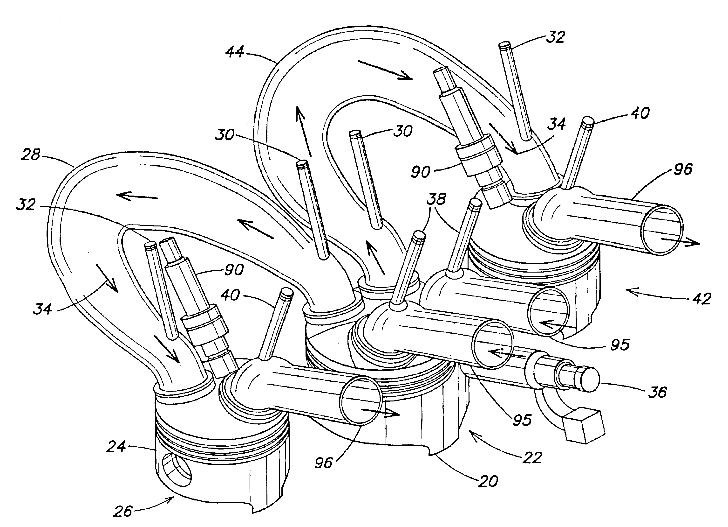
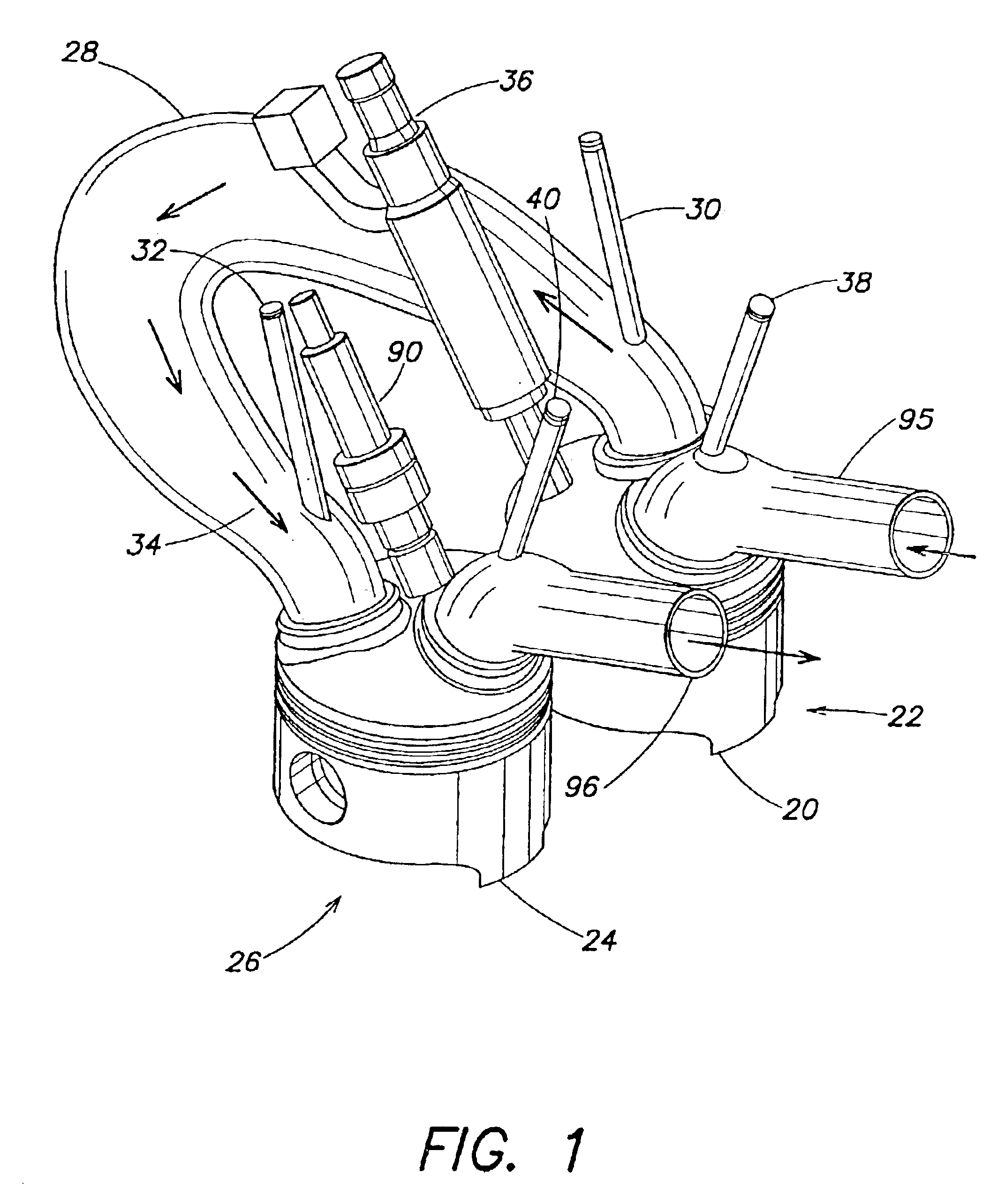
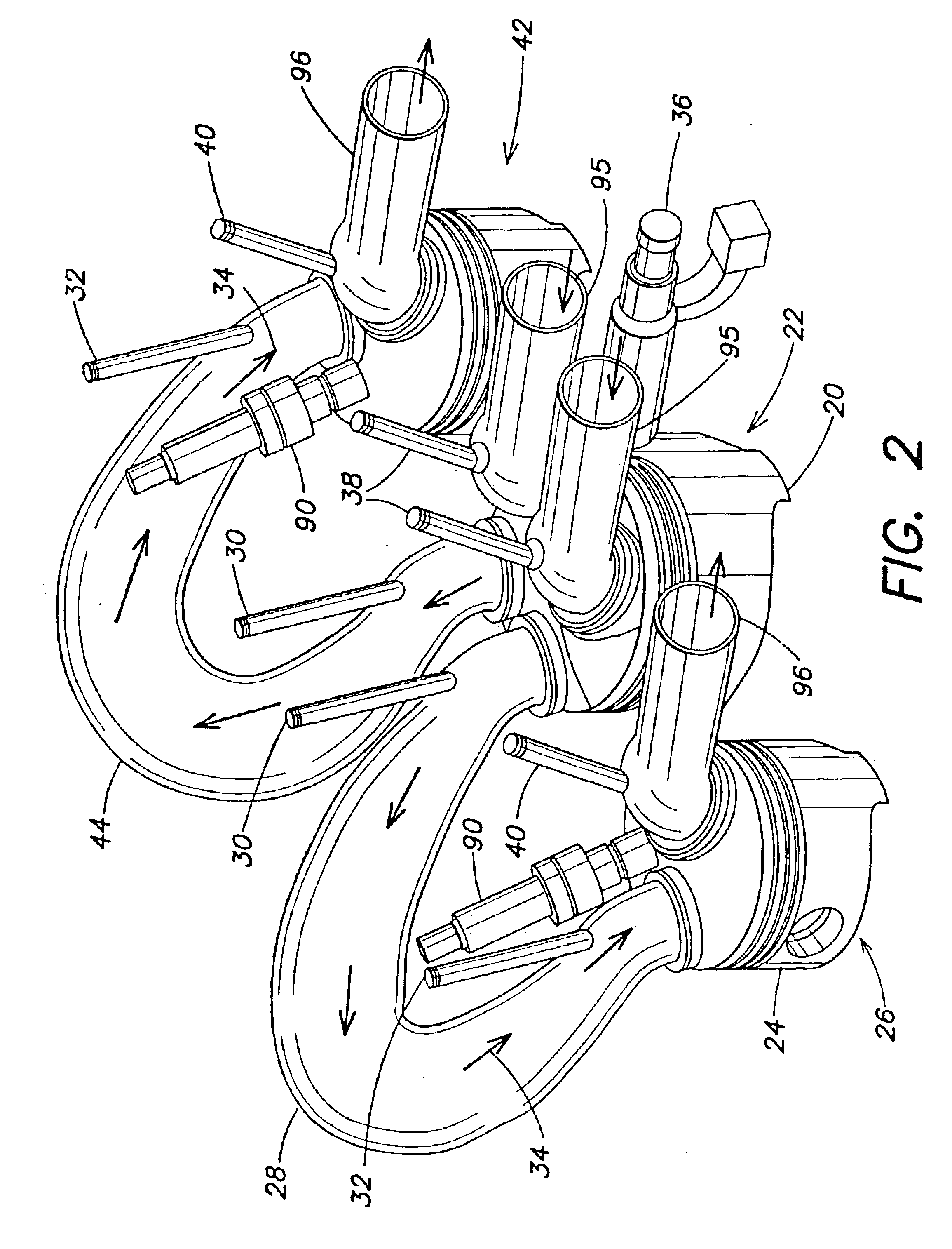
[0048]The engine of the present invention has been conceived through an axiomatic design process, resulting in an engine that achieves improved emission characteristics. The engine is constructed to have improved emissions characteristics by addressing many of the causes of emissions found in conventional engines. The engine may include one or more features, each independently or in combination, contributing to improved emissions characteristics when the engine is in operation. Although employing a particular design process (i.e., axiomatic design) to develop the engine of the present invention, the present invention is not limited in this respect, as other design processes may be employed.

[0049]The engine comprises a mixing cylinder for mixing and compressing air and fuel, and a second cylinder for further compressing the mixture, combusting the air and fuel mixture and exhausting it from the engine. A conduit provides fluid communication between the mixing cylinder and the power c...


PUM


Abstract

An internal combustion engine that has a pair of cylinders each having a reciprocating piston connected to a crank shaft by a connecting rod. One of the cylinders is adapted for an air and fuel intake and a compression strokes only, and the other of the cylinders adapted for at least power and exhaust strokes. A conduit exists for transfer of gases from the one into the other cylinder after the compression stroke. The conduit has means for isolating gases in the conduit intermediate the compression and power strokes. Furthermore, the conduit is designed to prevent the transfer of liquefied fuel from the one cylinder to the other.

Description

CROSS REFERENCE TO RELATED APPLICATIONS[0001]This application claims the benefit of and is a Continuation-In-Part of U.S. patent application Ser. No. 10 / 209,464, filed Jul. 30, 2002, now U.S. Pat. No. 6,789,514 which claims the benefit of U.S. Provisional Patent Application Nos. 60 / 308,959 filed Jul. 30, 2001, 60 / 313,123 filed Aug. 16, 2001, 60 / 317,693 filed Sep. 6, 2001, and 60 / 346,228 filed on Oct. 24, 2001.FIELD OF THE INVENTION[0002]The present invention relates to an internal combustion engine, and more particularly to a decoupled internal combustion engine whereby the mixing and compressing of air and fuel occurs within a first cylinder and power is derived from the second cylinder.BACKGROUND OF THE INVENTION[0003]The engine development process has often involved making decisions between competing engine characteristics, including fuel efficiency, power output, physical size, emission characteristics, reliability, and durability to name a few. In particular, emission character...

Claims


Application Information

Patent Timeline
Patent Type & Authority Patents(United States)
IPC IPC(8): F02B75/20F02B33/44F02B33/22F02B33/02F02B75/00F02B11/00
CPCF02B11/00F02B75/20F02B33/44F02B33/22
Inventor SUH, NAM P.CHO, NAM-HYO
Owner MASSACHUSETTS INST OF TECH
Why Eureka
Try Eureka