
Non-stop continuous stepped AC voltage regulator

A technology of voltage regulation device and AC circuit, which is applied in the direction of conversion equipment that can be converted into DC without intermediate conversion, can solve problems such as adverse effects of loads, and achieve the effect of improving power supply quality

Inactive Publication Date: 2004-06-02
何宪瑞
View PDF0 Cites 1 Cited by
  • Summary
  • Abstract
  • Description
  • Claims
  • Application Information

AI Technical Summary

Problems solved by technology

During an adjustment process, the output voltage jumps twice before and after, which will bring adverse effects to the load

Method used


Image

  • Non-stop continuous stepped AC voltage regulator
  • Non-stop continuous stepped AC voltage regulator
  • Non-stop continuous stepped AC voltage regulator

Examples


Embodiment Construction

[0015] The present invention will be further described below in conjunction with the accompanying drawings and embodiments.

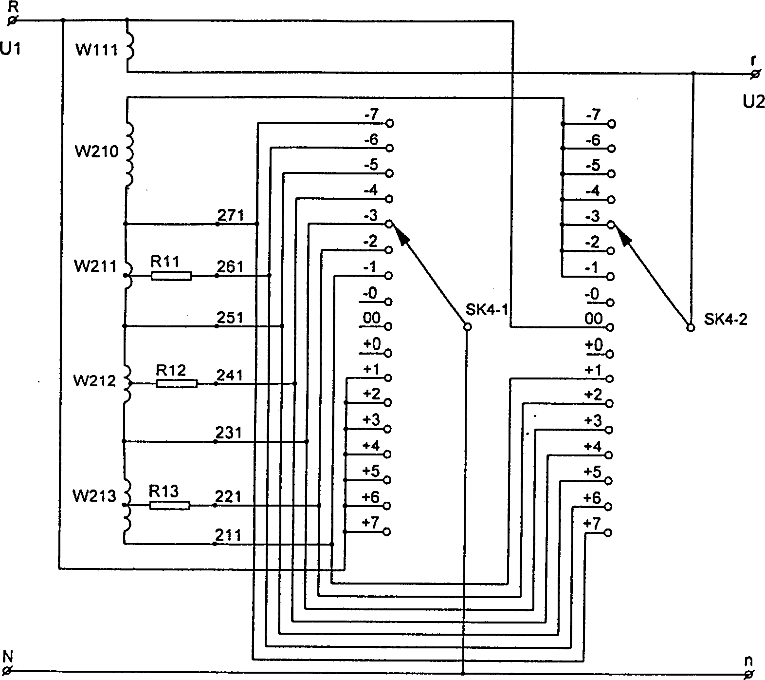
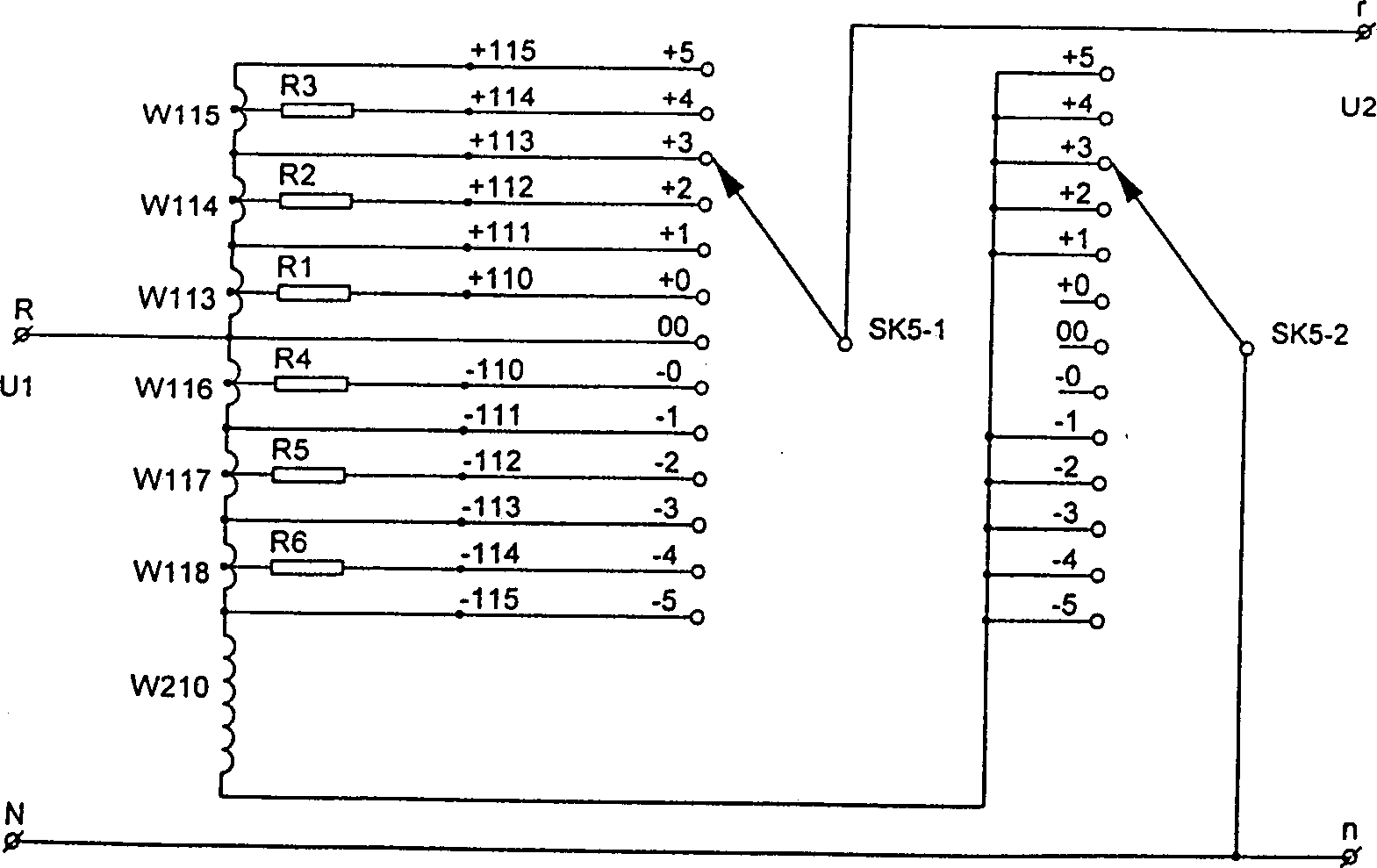
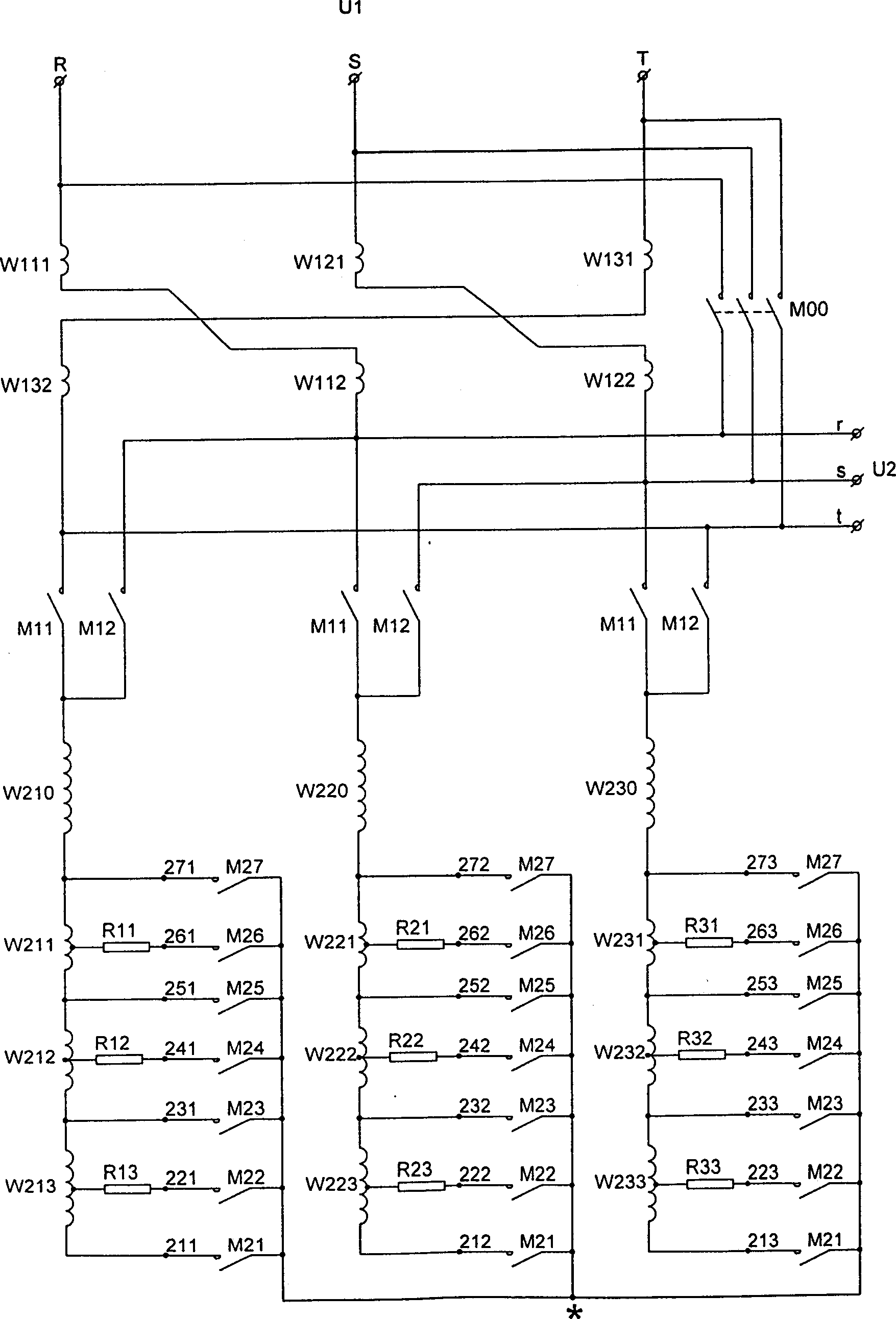
[0016] First, see figure 1 and figure 2 , figure 1 and figure 2 They are respectively the embodiments of the single-phase circuit excitation winding voltage regulation and output winding voltage regulation manual switch control circuit, using the manual transfer switch SK 4 、SK 5 The principle of direct switching winding voltage regulation is similar to the manual switch control circuit of three-phase circuit excitation winding voltage regulation. figure 2 Middle SK 5 Turn this bit counterclockwise for buck mode; turn this bit clockwise for boost mode. exist image 3 and Figure 4 , the winding W 111 , W 112 ;W 121 , W 122 ;W 131 , W 132 It is the output winding connected in series with the load, respectively wound on the two adjacent cores of the autotransformer core, R, S, T are the input terminals of the power supply, U 1 Represents...


PUM


Abstract

This invention relates to an AC continuous step-by-step voltage without switch-off modulation device contains a control device and voltage modulation device with the characteristics: series contacts of voltage modulation winding W211-213, W221-223 and W231-233 on each basic excitation winding W210, W220, and W230 are voltage modulation operation nodes controlled by contactors M21, M23, M25 and M27, form each voltage modulation device. The outer end of resistors R11-13, R21-23 and R31-31 connected with taps of each voltage modulation winding are transition contacts of voltage modulation to realize the voltage modulation of continuous step-by-step without switch-off or through modes by the change-over-switch SK2 or the automatic circuit controlling each voltage modulation device switched by the transition contact bridge.

Description

technical field [0001] The invention relates to a voltage regulating device, in particular to a continuous step-by-step voltage regulating device for an AC circuit without power failure. Background technique [0002] The voltage adjustment devices introduced in some patent documents disclosed in recent years are mostly changed to adjust the number of turns of the autotransformer excitation winding (or common winding) to change the output voltage. This method makes the operating current of the control circuit much smaller than the load current, thereby greatly reducing the control cost and making the control device easy and convenient to manufacture. Therefore, this method is generally valued by the industry. The corresponding power-saving device and Compensation devices and voltage regulators have also been valued and applied. The method for adjusting the number of turns of the excitation winding by the above-mentioned device is mostly to connect the excitation winding in s...

Claims


Application Information

Patent Timeline
Patent Type & Authority Patents(China)
IPC IPC(8): H02M5/12
Inventor 何宪瑞
Owner 何宪瑞
Learn More