Microwave oven

A microwave oven and microwave technology, applied in microwave heating, electric/magnetic/electromagnetic heating, electrical components, etc., can solve problems such as difficult heating methods, and achieve the effect of improved left-right symmetry and large degrees of freedom

Inactive Publication Date: 2004-06-16
WHIRLPOOL CORP
View PDF1 Cites 0 Cited by
  • Summary
  • Abstract
  • Description
  • Claims
  • Application Information

AI Technical Summary

Problems solved by technology

Although it is to some extent computationally possible to obtain a so-called cavity resonant mode in a cuboid, it has proven difficult to achieve a reasonably symmetrical heating pattern in such a cavity, especially when it is when feeding

Method used


Image

  • Microwave oven
  • Microwave oven
  • Microwave oven

Examples


Embodiment Construction

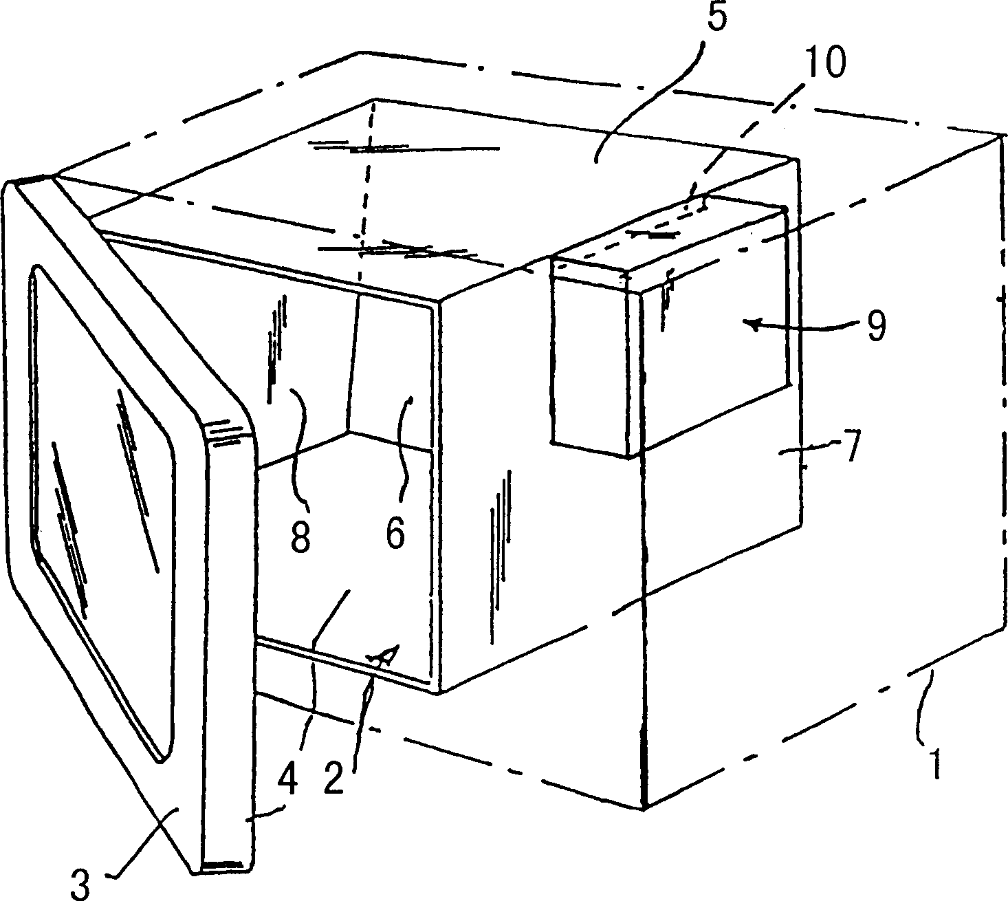
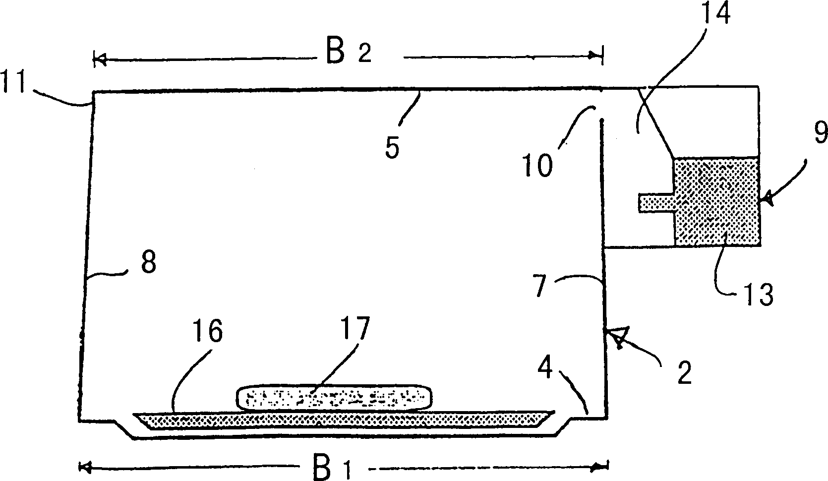
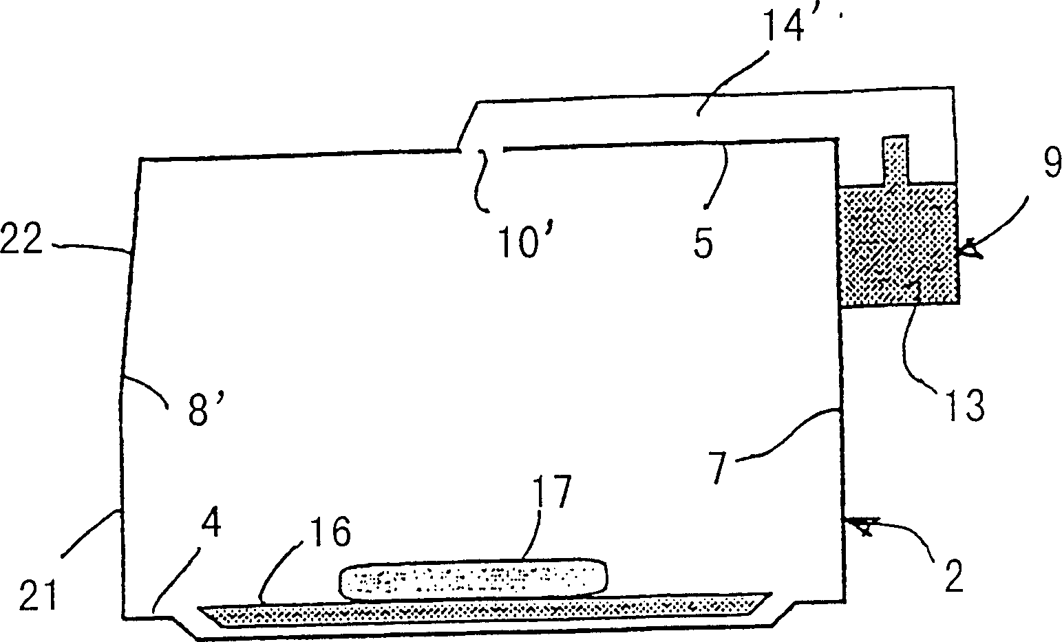
[0039] figure 1 and figure 2 The illustrated embodiment of the microwave oven according to the invention comprises an outer housing 1 , shown only roughly, and an oven cavity 2 , which is closed by means of a front door 3 . The cavity 2 consists of a horizontal cavity bottom 4 , a horizontal cavity top 5 , a vertical rear cavity wall 6 , a front vertical wall on the inside of the front door 3 and two cavity side walls 7 , 8 . exist figure 1 and figure 2 The right side wall 7 is vertical and equipped with a microwave device for feeding microwaves into the oven cavity through the slot-shaped rectangular side wall opening 10, for example as will be described in detail below. figure 1 and figure 2 The left side wall 8 is inclined somewhat inwardly and thus forms an angle of approximately 3° with respect to the vertical. Thus, apart from the inward slope of the side walls 8, the cavity is a cuboid. However, said inward slope is so small that no substantial difference from ...


PUM


Abstract

The invention discloses a microwave oven and a method for feeding microwaves into it. The rectangularly parallelepipedal oven cavity (2) has a side wall (8) with a slight inward slope which gives an upwardly decreasing horizontal cross section. By the selection of a suitable slope the mode balance in the cavity is affected so that the best equalisation of the heating pattern is obtained.

Description

technical field [0001] The invention relates to a microwave oven and a method for feeding microwaves into the microwave oven. Background technique [0002] Microwave ovens for domestic use and the like generally consist of a substantially cuboid cavity. This is due to manufacturing considerations and the general opinion that microwave ovens should be. Although it is to some extent computationally possible to obtain a so-called cavity resonant mode in a cuboid, it has proven difficult to achieve a reasonably symmetrical heating pattern in such a cavity, especially when it is when feeding. The heating method is usually improved by using so-called field stirrers or rotating bottom plates for loads. [0003] In similar cases, eg tunnel ovens for industrial microwave heating, geometries of vertical cross-section (transverse to the direction of transport through the oven) other than rectangular have been used. In such structures, it has been thought that the effect of the wall...

Claims


Application Information

Patent Timeline
Patent Type & Authority Patents(China)
IPC IPC(8): H05B6/74H05B6/64H05B6/80
CPCH05B6/6426H05B6/80
Inventor P·O·里斯曼D·卡尔松
Owner WHIRLPOOL CORP
Why Eureka
Try Eureka