A Microwave Oven

Active Publication Date: 2017-06-08
UNIVERSITÉ PARIS CITÉ +1
View PDF5 Cites 3 Cited by
  • Summary
  • Abstract
  • Description
  • Claims
  • Application Information

AI Technical Summary

Benefits of technology

[0010]One object of the present invention is to provide a micr

Problems solved by technology

A microwave oven often provides uneven heating of the material, because

Method used


Image

  • A Microwave Oven
  • A Microwave Oven
  • A Microwave Oven

Examples


Example

[0045]In the various figures, the same numeric references are used to indicate identical or similar elements.

MORE DETAILED DESCRIPTION

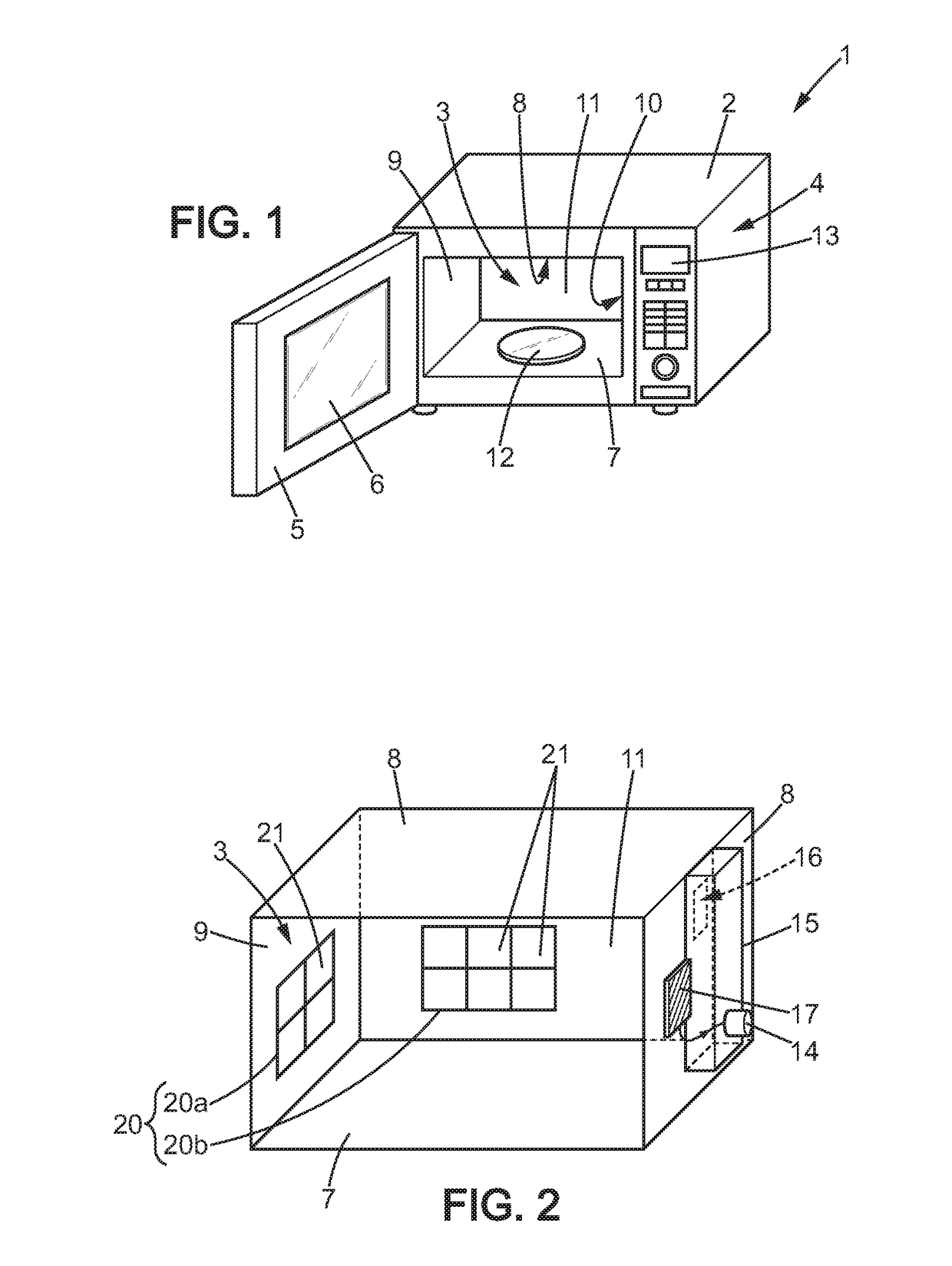
[0046]As illustrated on FIGS. 1 and 2, the microwave oven 1 includes:[0047]a casing 2 having a cavity 3 for heating a material placed into said cavity for heating said material, and an electric compartment 4 beside the cavity 3; and[0048]a door 5 hingeably connected to one side of the casing for opening and closing the cavity, the door eventually comprising a window 6 so as a user can see the material inside the cavity when the door is closed.

[0049]The cavity 3 has a general parallelepiped shape, and comprises a bottom wall 7, a top wall 8 and three side walls, i.e. a left side wall 9, a right side wall 10, and a back side wall 11. All these walls are inner walls of the cavity.

[0050]The bottom wall 7 may optionally be equipped with a turntable device 12 for rotating the material during the heating.

[0051]The electric compartment 4 comprises:[0052]a fro...


PUM


Abstract

A microwave oven comprising a cavity in which a material can be placed for heating and a magnetron for generating a microwave. The microwave oven further comprises an electromagnetic element adapted to interact with microwaves into the cavity and a control unit that provides a control signal to the electromagnetic element for modifying an impedance of the electromagnetic element during time of heating.

Description

FIELD OF THE INVENTION[0001]The present invention relates to a microwave oven, and more particularly, a microwave oven in which heating is electronically substantially uniform inside a cavity.BACKGROUND OF THE INVENTION[0002]The present invention concerns more precisely a microwave oven comprising:[0003]a cavity in which a material can be placed for heating,[0004]a magnetron for generating a microwave, said magnetron being in communication with the cavity for propagating the microwaves from the magnetron to the cavity.[0005]A microwave oven often provides uneven heating of the material, because the microwave radiation is not uniformly distributed inside the cavity. The microwaves are standing electromagnetic waves inside the cavity. The electric field inside the cavity comprises high variations in intensity, forming nodes concentrating the electric energy and antinodes with very small electric energy. This leads to heating variations from one location to an other location inside the...

Claims


Application Information

Patent Timeline
IPC IPC(8): H05B6/64H05B6/74H01P1/20H05B6/70
CPCH05B6/6452H01P1/2005H05B6/74H05B6/705H01Q3/44H01Q15/002Y02B40/00
Inventor LEROSEY, GEOFFROYFINK, MATHIASKAINA, MADEGEDUPRE, MATHIEU
Owner UNIVERSITÉ PARIS CITÉ
Why Eureka
Try Eureka