Apparatus and method for controlling heating lamp of rapid heat treatment equipment

Inactive Publication Date: 2011-10-20
ASIA PACIFIC SYST
View PDF2 Cites 3 Cited by
  • Summary
  • Abstract
  • Description
  • Claims
  • Application Information

AI Technical Summary

Benefits of technology

[0007]According to an exemplary embodiment, a calibration value for each of the subgroups with respect to graph data of input voltage-reference input current is previously obtained and actual input current applied to each of the subgroups in actual

Problems solved by technology

Currently, the difference in heating characteristics between the heat lamps is not calibrated.
Accordingly, even when the same voltag

Method used


Image

  • Apparatus and method for controlling heating lamp of rapid heat treatment equipment
  • Apparatus and method for controlling heating lamp of rapid heat treatment equipment
  • Apparatus and method for controlling heating lamp of rapid heat treatment equipment

Examples


Embodiment Construction

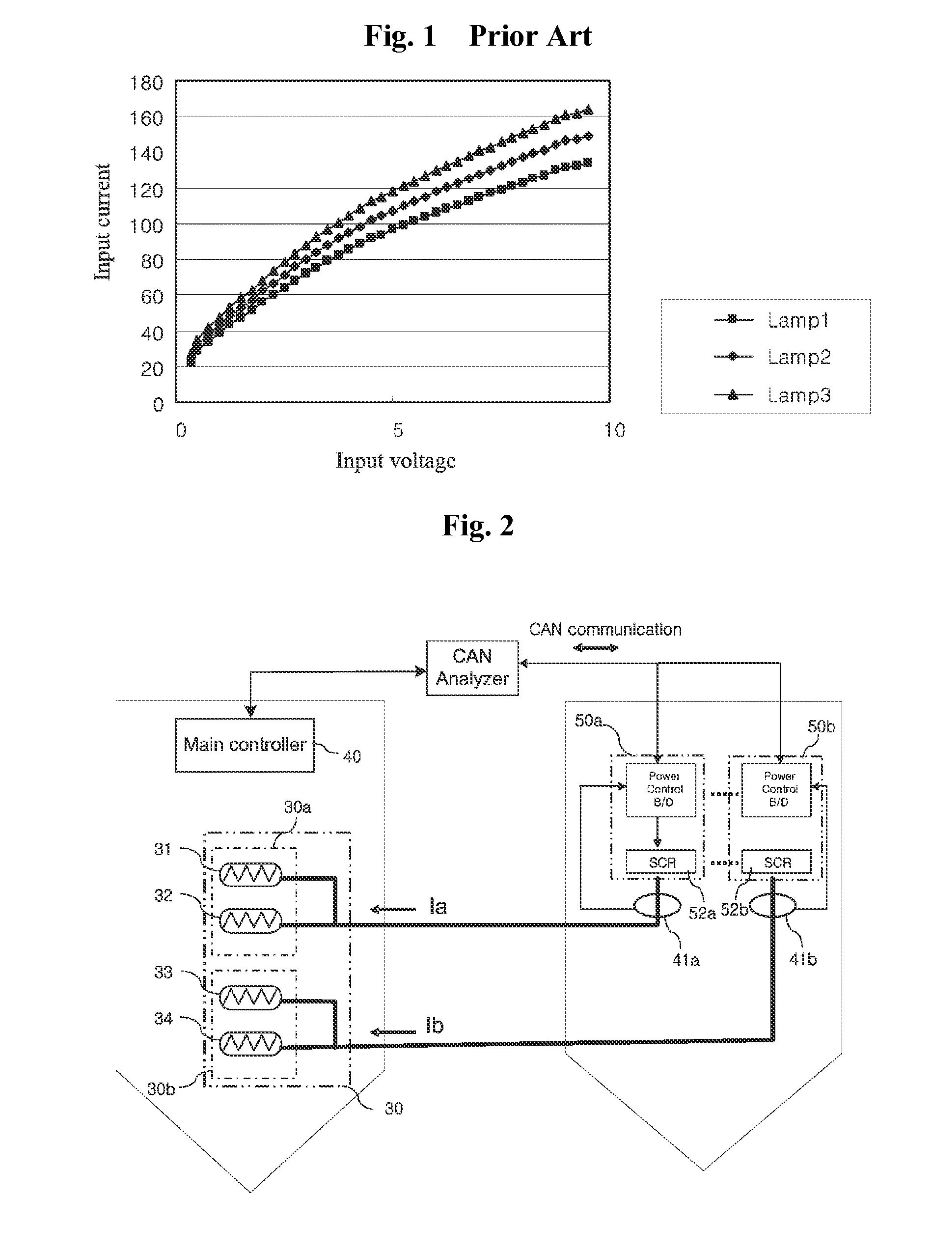
[0011]Exemplary embodiments of the invention will be described in detail. However, it should be understood that the embodiments are given to provide thorough understanding of the invention to those skilled in the art and may be embodied in different ways. Thus, the present invention should not be construed as being limited thereto. Herein, the term “graph data” refers to pairs of coordinates of input voltage to input current, which can be depicted by a graph, as defined in the description of the background art.

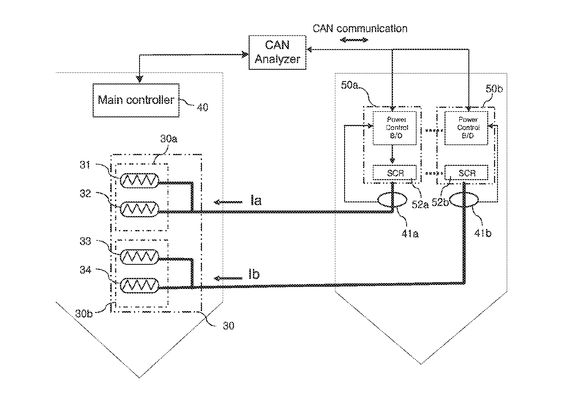
[0012]FIG. 2 is a view of an apparatus for controlling heat lamps of rapid heat treatment equipment according to an exemplary embodiment of the invention, and

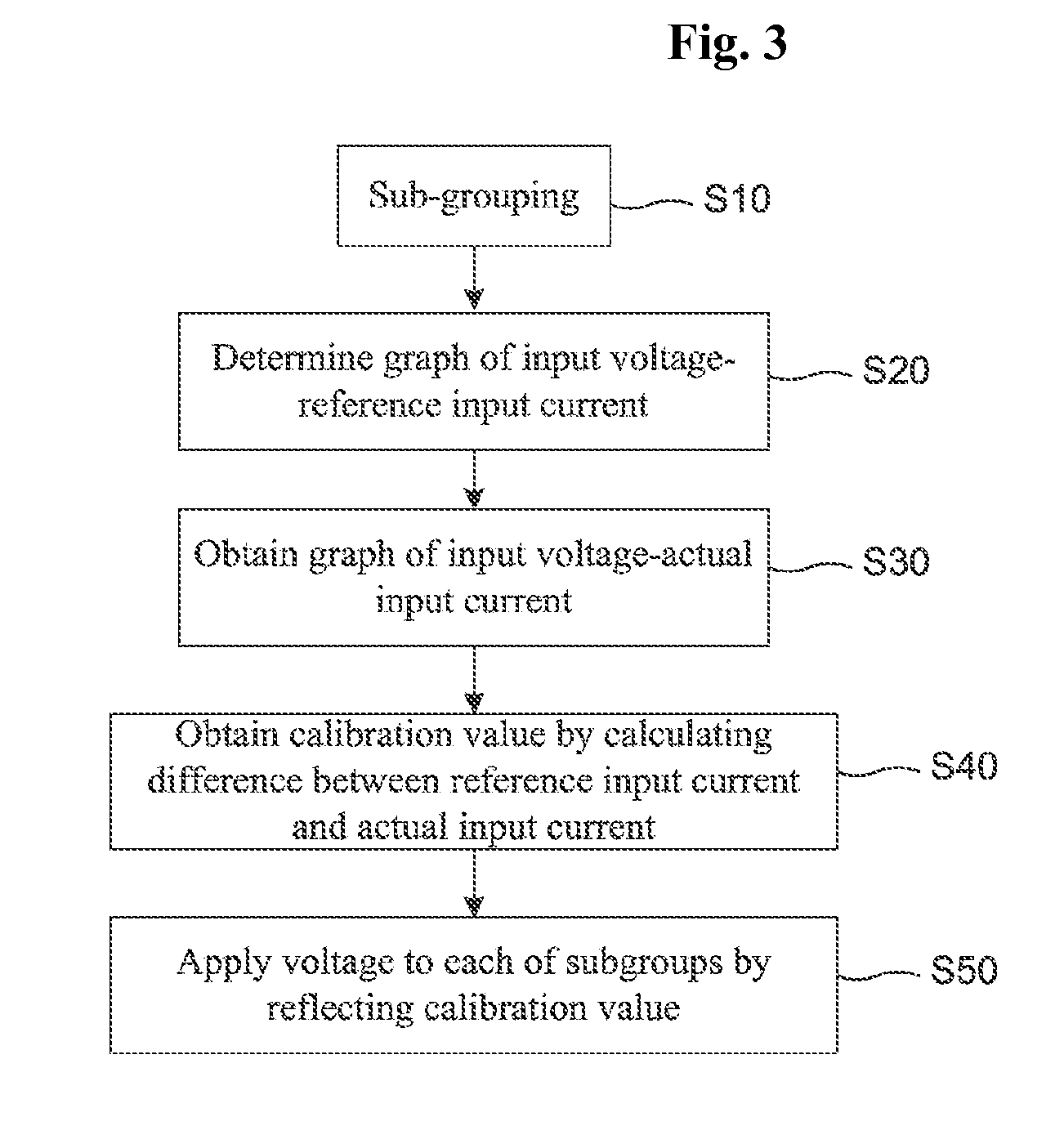
[0013]FIG. 3 is a flowchart of a method of controlling heat lamps of rapid heat treatment equipment according to an exemplary embodiment of the invention.

[0014]Referring to FIGS. 2 and 3, a heat lamp group 30 comprising a plurality of heat lamp 31, 32, 33, 34 is divided into a plurality of subgroups 30a, 30b, and power co...


PUM


Abstract

The method of the present invention for controlling a heating lamp of rapid heat treatment equipment comprises: a step wherein a heating lamp group is divided into a plurality of subgroups to determine graphical data regarding input voltage versus the reference input current that is applied to the subgroups uniformly; a step wherein actual input current respectively applied to each group is measured to obtain graphical data regarding input voltage versus actual input current; a step wherein a difference value for calibration of each subgroup is obtained from the difference between the reference input current and the actual input current; and a step wherein the difference value for calibration is reflected to apply a voltage to said subgroup individually. According to the present invention, substrate heating takes place uniformly because differences of calibration are reflected in actual input current to apply a voltage to a subgroup.

Description

TECHNICAL FIELD[0001]The present invention relates to an apparatus and method for controlling heat lamps of rapid heat treatment equipment. More particularly, the present invention relates to an apparatus and method for controlling heat lamps of rapid heat treatment equipment, in which a group of heat lamps is divided into a plurality of subgroups such that electric power is independently supplied to each of the subgroups to enhance heating uniformity during rapid heat treatment of a substrate.BACKGROUND ART[0002]Rapid heat treatment equipment heats a substrate through a plurality of heat lamps. Here, although the heat lamps are manufactured by the same company, there is a slight difference in heating characteristics therebetween. Currently, the difference in heating characteristics between the heat lamps is not calibrated.[0003]FIG. 1 is a graph illustrating a difference in heating characteristics between heat lamps. As shown in FIG. 1, although Lamp 1, Lamp 2 and Lamp 3 are manufa...

Claims


Application Information

Patent Timeline
IPC IPC(8): F27D11/00
CPCH05B3/0033H05B1/02
Inventor JI, SANG HYUNLEE, DAE YONGLEE, SEUNG HWAN
Owner ASIA PACIFIC SYST
Why Eureka
Try Eureka