Fusing apparatus and image forming apparatus provided with the same, and heating apparatus
Active Publication Date: 2012-02-23
SHARP KK
View PDF5 Cites 3 Cited by
Summary
Abstract
Description
Claims
Application Information
AI Technical Summary
This helps you quickly interpret patents by identifying the three key elements:
Problems solved by technology
Method used
Benefits of technology
Benefits of technology
[0021]The present invention has been accomplished based upon the above-mentioned knowledge that has been found by the present inventors, and aims to provide a stable and robust fusing apparatus that can attain a uniform heating, while achieving power saving and shortening the warm-up time, and that is not broken or that is not defective. More specifically, in the fusing apparatus having a configuration in which a sheet heating element is pressed against a rigid member serving as a heat-conductor, an appropriate position for pressing the sheet heating element is selected, whereby a uniform heating and a robust and stable configuration can be realized.
Problems solved by technology
However, a thermal conductivity of the elastic layer of the elastic roller is extremely low.
When the thickness of the elastic layer of the elastic roller increases in a structure in which the heating unit is provided in the elastic roller as in the conventional case, a thermal conductivity from the inside of the elastic roller to the surface thereof is deteriorated, which might increase a warm-up time.
However, the recovery of the temperature of the fuser roller, which is reduced at the sheet passing portion, is too late, which entails a problem that the temperature of the fuser roller cannot follow the fusing temperature.
When the diameter of the elastic roller is increased in order to secure the time for the temperature recovery, a power consumption of the heating unit might increase.
When the pressure position is close to the conduction portion in this case, the substrate thermally expands at the adjacent conduction portions to warp, with the result that a gap is formed between the sheet heating element and the heat-conductor.
When the gap is locally formed in the longitudinal direction of the substrate, a transfer of the heat at this portion is hindered, resulting in that the temperature of the sheet heating element is locally increased.
If so, this portion further expands thermally, which causes a significant warp.
In an extreme case, the substrate is broken, or the resistance heating layer is fused by the heat, so that a uniform heat generation cannot be attained.
Although the substrate is not broken or the substrate does not become defective, a problem arises in which a temperature unevenness is caused in the longitudinal direction of the substrate.
Although the substrate is not broken or the substrate does not become defective, a problem arises in which a temperature unevenness is caused in the longitudinal direction of the substrate.
These problems are unique to the present structure in which the sheet heating element is pressed against the rigid member.
WO99 / 00713 describes the configuration in which the sheet heating element is pressed against the pressure roller, which is the elastic member, via the fuser belt, so that this configuration is disadvantageous in power saving and shortening the warm-up time.
However, the deformation of the sheet heating element due to the warp is absorbed by the pressure roller, which is the elastic member, so that a gap is difficult to be formed.
Method used
Image
Click on the blue label to locate the original text in one second.
Reading with bidirectional positioning of images and text.
Examples
embodiment 1
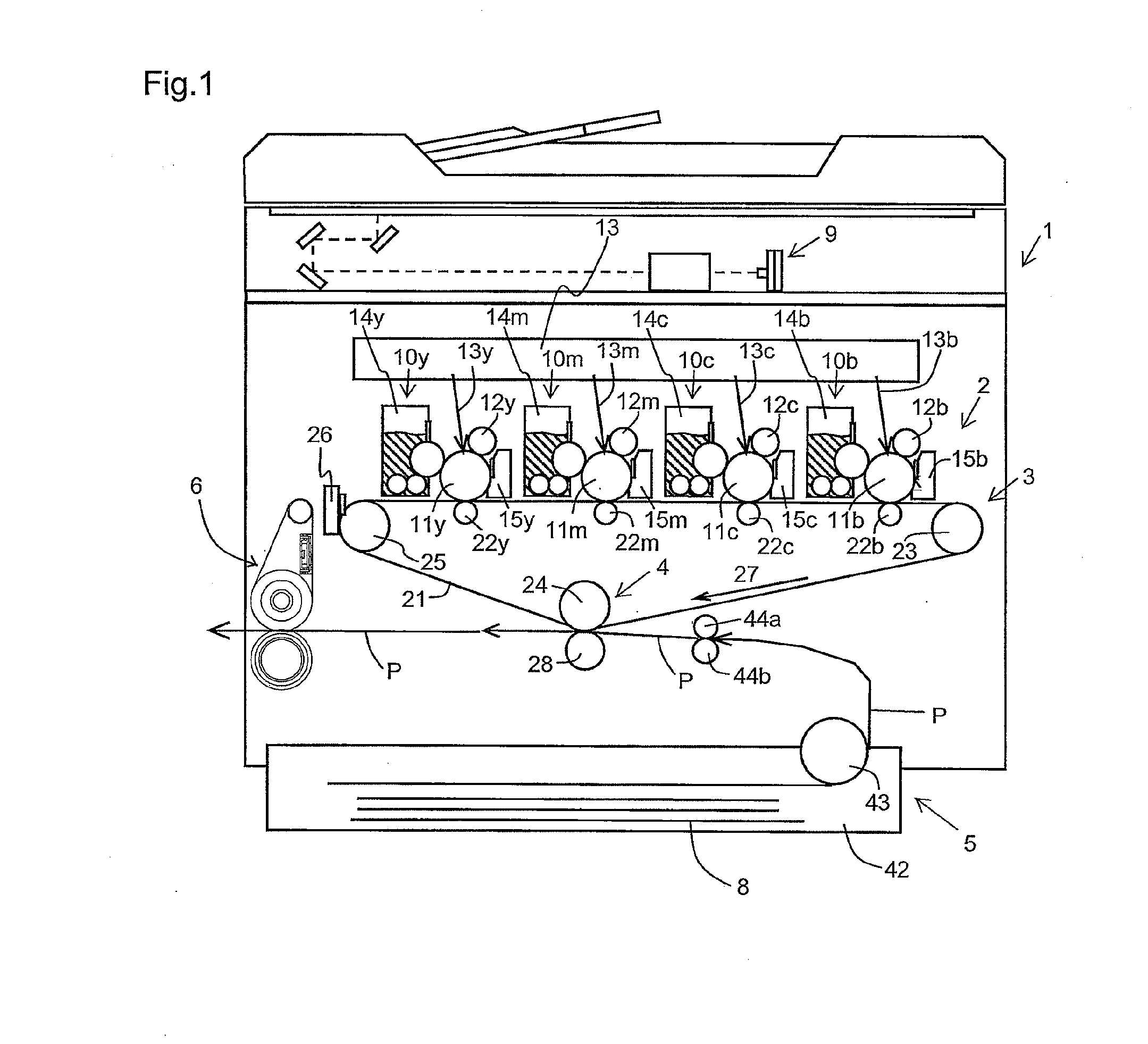
[0066]FIG. 1 is a diagram schematically illustrating a configuration of an image forming apparatus 1 that is one embodiment of the present invention. The image forming apparatus 1 includes an image forming portion 2, an intermediate transfer portion 3, a secondary transfer portion 4, a recording medium feeding portion 5, and a fusing portion 6 that is a fusing apparatus according to the present invention, as well as a display portion, an operation portion, and a control portion, which are not illustrated in FIG. 1.
[0067]The fusing portion 6 will be described below. The detailed configurations of the other portions will be described at the end of this specification.
(Fusing Portion)
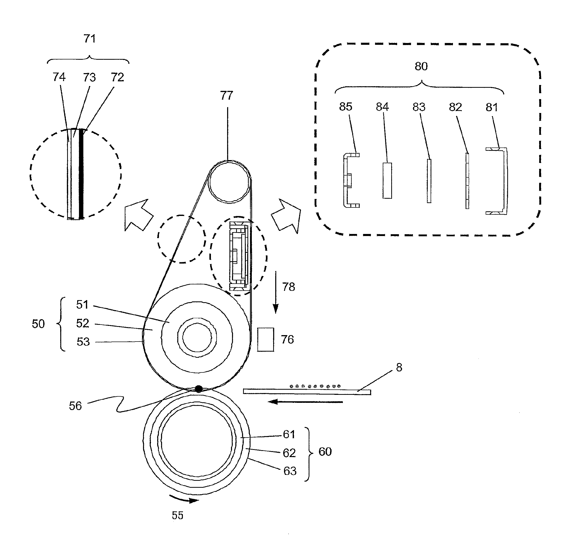
[0068]FIG. 3 is a sectional view illustrating the configuration of the fusing portion 6. The fusing portion 6 serving as a fusing unit includes a fuser belt 71, a fuser roller 50, a tension roller 77, a heating member 80, and a pressure roller 60.
[0069]The fuser belt 71 is an endless belt-like member that i...
experimental example 1
[0112]An experiment described below was carried out in order to confirm an affect by an end of a wiring pattern of a sheet heating element and a pressure position.
[0113]The specification of the sheet heating element and the heat-conductor used in the experiment and the pressure position were as stated below.
Sheet heating element: 366 mm (wiring pattern: 320 mm) (the center of the substrate and the center of the wiring pattern agree with each other)
Position of conduction portion: 60 mm, 127 mm, 194 mm, 261 mm (a position of a start of a wiring pattern at one side is defined as 0)
Heat-conductor: 320 mm
[0114]Position where pressure member is arranged: 90, 110, 150, 170, 210, 230 mm (fixed)
[0115]The pressure position from the end of the wiring pattern of the sheet heating element was changed as 0, 5, 10, 15, and 30 mm (see FIG. 6). The outward direction from the end of the wiring pattern of the sheet heating element was specified as minus, wherein the pressure member was arranged at −5,...
experimental example 2
[0120]An experiment similar to the experiment 1 was carried out except that the length of the heat-conductor was extended by 5 mm (FIG. 7). Table 2 shows the result.
[0121]Since the heat-conductor was extended by 5 mm, the position where the sheet heating element warped was extended by 5 mm. Therefore, it was considered that the result of the pressure position was shifted by 5 mm. As the heat-conductor is extended more and more from the end of the wiring pattern, heat is more derived, whereby the temperature drop at the end becomes significant. Extending the heat-conductor by 10 mm or more adversely affects the fusing temperature at the end.
TABLE 2Length ofPosition of pressureheat-conductormemberResult+5−15X−10Δ−5◯0◯
PUM
Abstract
A fusing apparatus that including a sheet heating element for generating heat to fix a toner image being transferred onto a sheet; an endless belt; a rigid member for conducting the heat to the endless belt and being arranged to contact with the sheet heating element and the endless belt respectively; and a pressure member for pressing the sheet heating element against the rigid member, wherein the endless belt is arranged to contact with the sheet, the sheet heating element includes an elongated substrate extending in a widthwise direction of the endless belt, plural resistance heating layers which are formed on a surface of the substrate along a longitudinal direction thereof and arranged parallel to one another, and at least one conduction portion formed in at least one place of an intermediate region between one end and another of each resistance heating layer to connect the different resistance heating layers, and the pressure member presses the sheet heating element against the rigid member at a position other than a position where the conduction portion is formed.
Description
CROSS-REFERENCE TO RELATED APPLICATION[0001]This application is related to Japanese Patent Application No. 2010-184285 filed on Aug. 19, 2010, whose priority is claimed and the disclosure of which is incorporated by reference in its entirety.BACKGROUND OF THE INVENTION[0002]1. Field of the Invention[0003]The present invention relates to a fusing apparatus used in an electrophotographic system, an image forming apparatus provided with the same, and a heating apparatus having a sheet heating element.[0004]2. Description of the Related Art[0005]An image forming apparatus using an electrophotographic process (hereinafter merely referred to as an “image forming apparatus”) includes a photoconductor, a charging unit, an exposure unit, a developing unit, a transfer unit, and a fusing unit, for example. The image forming apparatus performs a charging process, an exposure process, a developing process, a transfer process, and a fusing process with the use of the photoconductor and these unit...
Claims
Application Information
Patent Timeline
Application Date:The date an application was filed.
Publication Date:The date a patent or application was officially published.
First Publication Date:The earliest publication date of a patent with the same application number.
Issue Date:Publication date of the patent grant document.
PCT Entry Date:The Entry date of PCT National Phase.
Estimated Expiry Date:The statutory expiry date of a patent right according to the Patent Law, and it is the longest term of protection that the patent right can achieve without the termination of the patent right due to other reasons(Term extension factor has been taken into account ).
Invalid Date:Actual expiry date is based on effective date or publication date of legal transaction data of invalid patent.

