Unlock instant, AI-driven research and patent intelligence for your innovation.

Device for testing yarn tension and yarn sensor

A technology of yarn tension and yarn, which is applied in the field of yarn sensors, can solve the problems of not being able to measure speed, yarn staying, and yarn misclassification, etc.

Inactive Publication Date: 2004-09-29
TORAY ENG CO LTD
View PDF0 Cites 0 Cited by
  • Summary
  • Abstract
  • Description
  • Claims
  • Application Information

AI Technical Summary

Problems solved by technology

[0005] A first problem in the above-mentioned device for detecting yarn tension is that if the distance between the yarn position sensor and the yarn guide position sensor is small, the measurement time becomes too short to obtain the desired accuracy measurement speed, unless the time measurement accuracy is increased
[0006] And, the second problem is: when the transverse guide reverses it, the yarn tension rises in the direction of instantaneous movement, and the increased value is measured as the average tension value
[0007] Furthermore, the third problem is that if the yarn position sensor is arranged closer to the apex guide so that the distance between the yarn position sensor and the guide position sensor becomes longer to solve the first and second problems, then Yarn displacement at the yarn detection position is small causing the yarn to stay within the detection range of the yarn position sensor, whereby the bent portion of the yarn cannot be accurately detected
[0012] If it is impossible to detect the yarn, the measured tension value is judged to be abnormal, which leads to a problem that a yarn with normal quality may be erroneously classified as having abnormal quality when performing yarn quality control according to the measured tension value

Method used


Image

  • Device for testing yarn tension and yarn sensor
  • Device for testing yarn tension and yarn sensor
  • Device for testing yarn tension and yarn sensor

Examples


Embodiment Construction

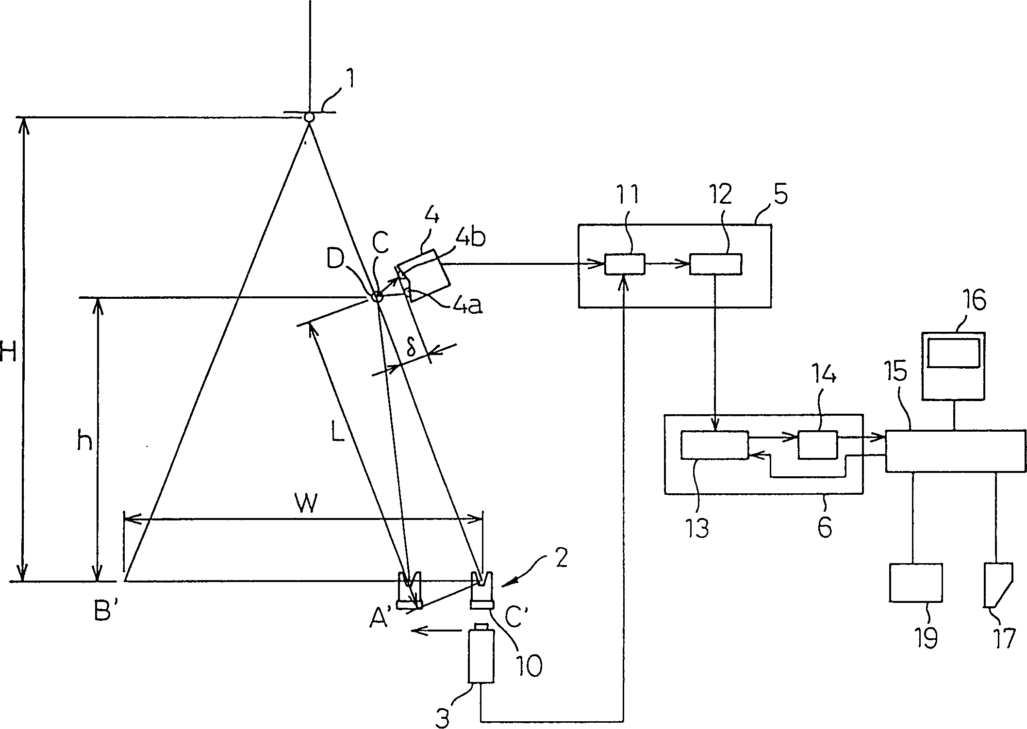
[0045] figure 1is a schematic diagram showing a device for detecting yarn tension according to an embodiment of the present invention. The device for detecting the tension of the yarn is arranged in a winder with an apex guide 1 for guiding the yarn and a traversing device 2 for reciprocating the yarn. The device includes: a yarn position sensor 4, arranged between the apex guide 1 and the traversing device 2, used to detect the transverse wave generated in the yarn by the movement of the traversing device 2; a yarn guide position sensor 3 , arranged near the traversing device 2 used to detect the yarn guiding position; the measuring device 5 is used to measure the shear wave according to the time period from the moment when the transverse wave is generated by the traversing device to the moment when the transverse wave is detected by the yarn position sensor The apparent propagation speed of the shear wave; the calculation device 6 is used to calculate the true propagation s...


PUM


Abstract

To provide a tension detecting device which can surely measure the average tension of a thread which is not affected by the tension rise of the thread caused by the inverting motion of the thread with accuracy without giving any influence to the quality of the thread. A tension detecting device is provided with a thread position detecting means which is positioned between a swinging fulcrum guide and a traverse device and detects the transverse wave caused by the device, a thread guiding position detecting means positioned near the device, and a measuring means which measures the apparent propagating speed of the transverse wave. The detecting device is also provided with an arithmetic means which calculates the real propagating speed of the transverse wave. In the tension detecting device, the thread position detecting means is set up at a position meeting a relation, 2H / 3 B65H 59 / 40 18 14 0 2000 / 5 / 26 1275522 2000 / 12 / 6 1168647 2004 / 9 / 29 2004 / 9 / 29 2004 / 9 / 29 Toray Industries, Inc. Japan Iwaide Suguru Imae Masazumi Aratani Tomosueko ma gao 11038 The Patent Agency of the Chinese Council for the Promotion of International Trade (CCPIT) No.1 Waidajie, Fuxingmen, Beijing 100086 Japan 1999 / 5 / 28 149344 / 1999 Japan 1999 / 5 / 28 149345 / 1999

Description

technical field [0001] The invention relates to a device for detecting the tension of a yarn, and a yarn sensor suitable for use in a device for producing yarn or the like. Background technique [0002] A device for detecting yarn tension in an apparatus for synthetic yarn production or other apparatus is known and disclosed in Japanese Unexamined Patent Publication (Kokai) No. H10-305966. [0003] The above device for detecting yarn tension includes: a yarn position sensor provided on an upstream side of a traversing device for detecting transverse waves generated in the yarn due to movement of the traversing device; a yarn guide position sensor , arranged near the traversing device, used to detect the position of the yarn guide; the measuring device, used to measure the time period from the moment when the transverse wave is generated to the moment when the transverse wave is detected by the yarn position sensor, measured by the traversing device an apparent propagation v...

Claims


Application Information

Patent Timeline
Patent Type & Authority Patents(China)
IPC IPC(8): D01H13/26B65H54/28B65H59/40G01L5/10
CPCB65H2553/41B65H54/2887B65H2701/31B65H59/40B65H54/2812G01L5/105D01H13/26
Inventor 岩出卓今江正澄新谷友季子
Owner TORAY ENG CO LTD