Rolling ball screw having cooling channel

A ball screw and cooling channel technology, which is applied in the manufacture of tools, feeding devices, friction transmission devices, etc., can solve the problems of ineffective cooling, inconvenient and limited application, and unfavorable machining accuracy of machine tools

Inactive Publication Date: 2004-11-10
HIWIN TECH
View PDF0 Cites 0 Cited by
  • Summary
  • Abstract
  • Description
  • Claims
  • Application Information

AI Technical Summary

Problems solved by technology

[0003] 1) Since the length of the screw of the general ball screw is much longer than the length of the nut, and the steel ball circulation system is set inside the nut, after the ball screw is running, the time per unit area inside the nut is in contact with the circulating steel ball than the time per unit area of ​​the screw and The contact time of circulating steel balls is much longer, so most of the heat generated by operation is concentrated on the nut, making the temperature of the nut relatively higher than the temperature of the screw, while the above-mentioned commonly used hollow ball screw can only directly cool the relatively low temperature. For the screw part, the nut part with higher temperature cannot be effectively cooled, and the overall cooling effect is not significant;
[0004] 2) The hollow ball screw is generally used in high-feed rate machine tools. Due to the difficulty in machining the axial inner hole, it is difficult to require the concentricity of the axial inner hole, so there is a periodic eccentricity during high-speed operation The force is generated, causing the vibration phenomenon of the machine table, which has a considerable adverse effect on the machining accuracy of the machine tool;
[0005] 3) Due to factors such as the length and outer diameter of the hollow screw, there are limitations in processing the axial inner hole, and the processing cost is relatively high, and the coolant inlet pipe and outlet pipe are located on both sides of the screw part, which takes up a large amount of space. Therefore, it is difficult to install in a narrow space, causing inconvenience and restrictions on application; and
[0006] 4) Limited by the outer diameter of the hollow screw, it is difficult for the coolant to form a backflow design in the hollow screw, and it can only pass through the hollow screw in one direction, so that the heat exchange time between the coolant and the screw is quite short, and the heat exchange rate is difficult to be effective promote

Method used


Image

  • Rolling ball screw having cooling channel
  • Rolling ball screw having cooling channel
  • Rolling ball screw having cooling channel

Examples


Embodiment

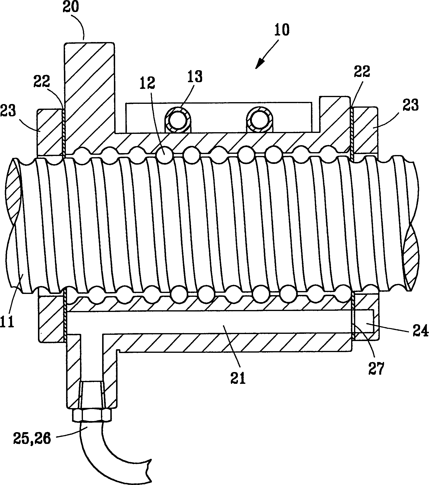
[0021] see figure 1 , the ball screw 10 provided by the present invention includes a screw 11 of a known form, a plurality of steel balls 12, a steel ball circulation system 13 and a nut 20 with several cooling through holes 21 of the main technical feature part of the present invention The steel ball 12 is placed between the screw 11 and the nut 20, and the steel ball circulation system 13 is used to make it circulate; when the screw 11 rotates, the nut 20 can be driven to make a linear movement through the steel ball 12, so that The ball screw 10 can be used, for example, as a feed device of a machine tool or the like.

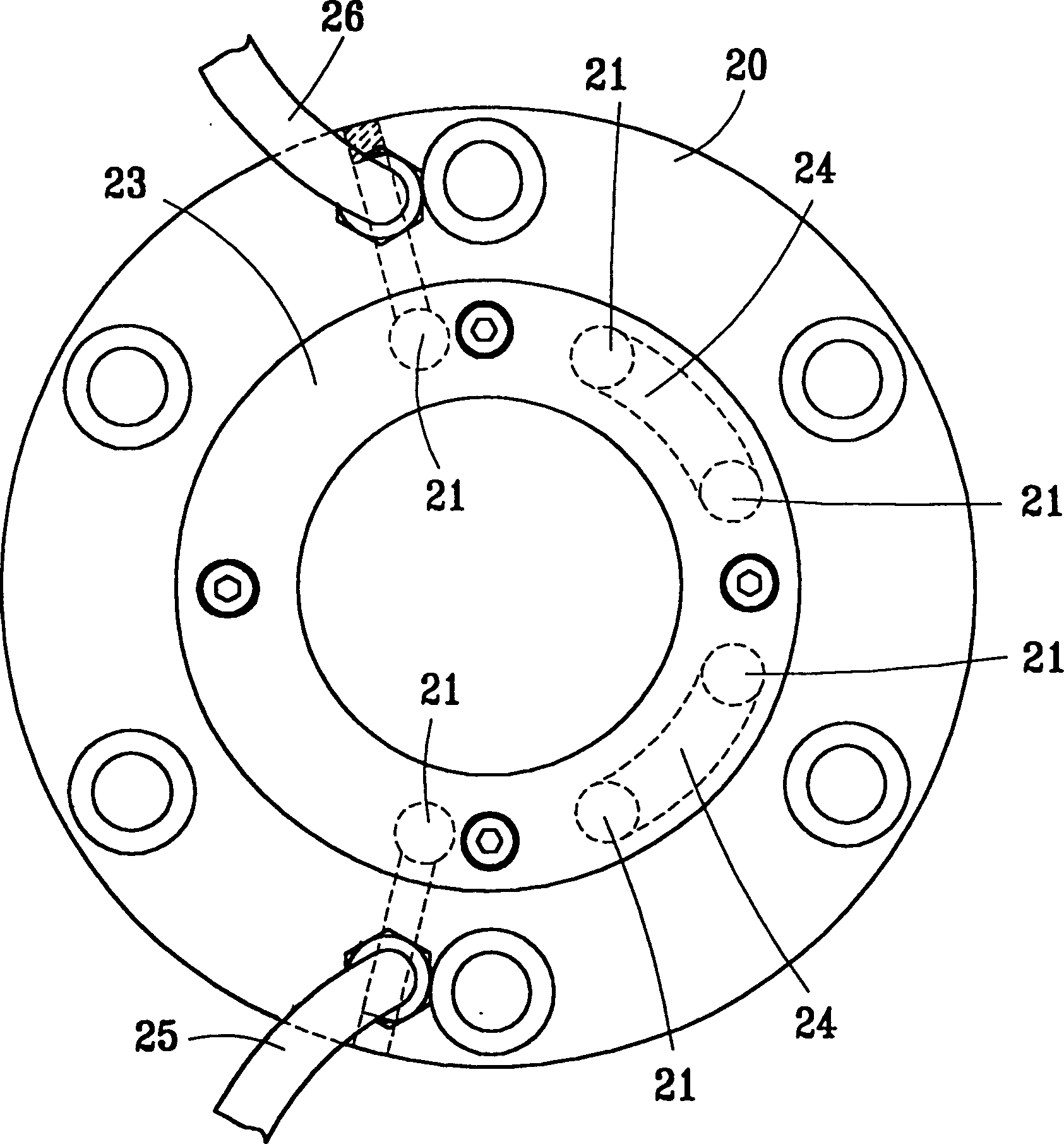
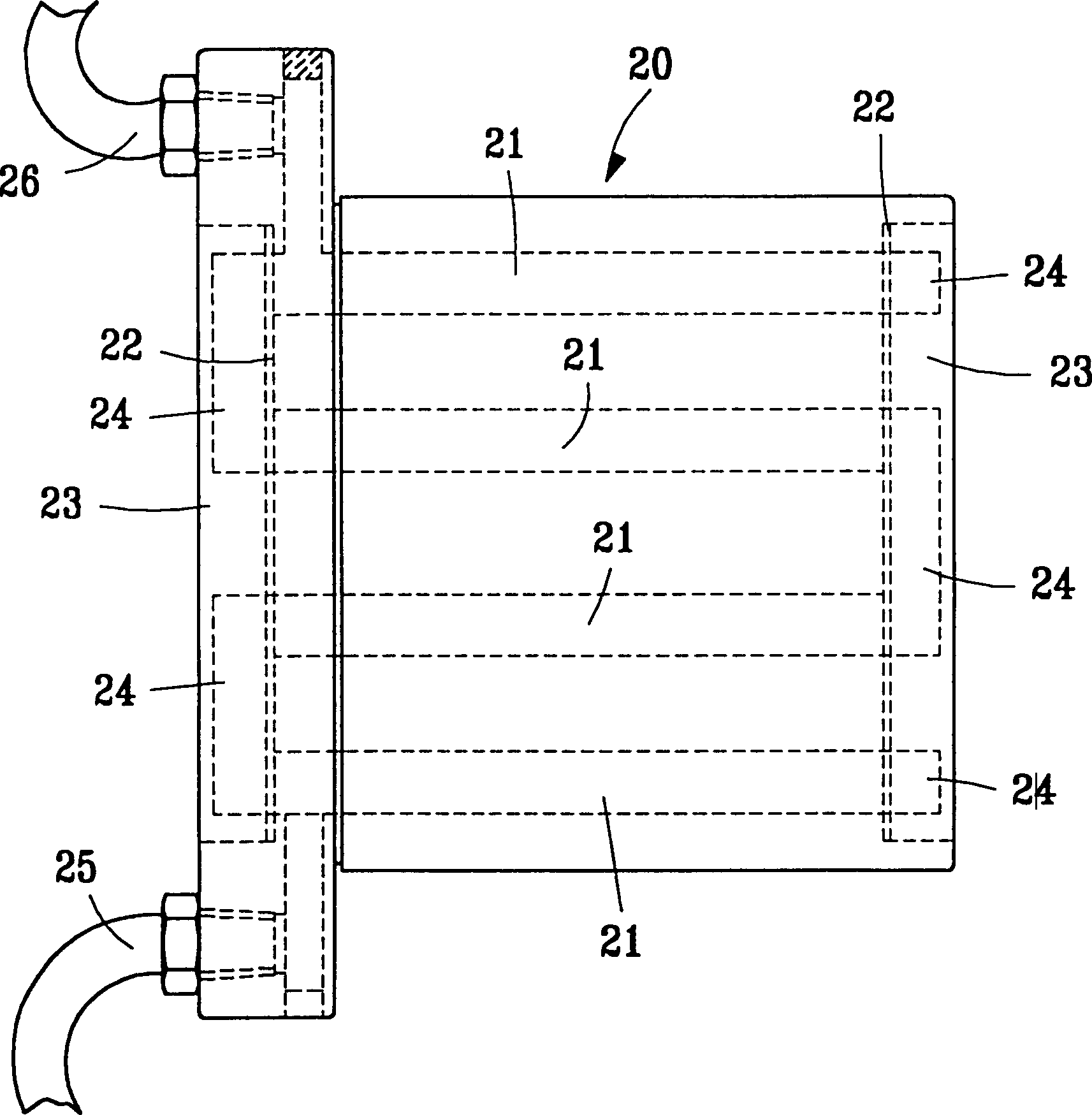
[0022] In the present invention, several cooling through holes 21 through the nut 20 are provided in the nut 20 along the axial direction, so that the cooling medium with a set working temperature value can enter the nut 20 and communicate with the nut. 20 for heat exchange to take away the heat generated between the nut 20 and the steel ball 12 due to cycl...


PUM


Abstract

The rolling ball screw has several screw nut with circular channel of cooling medium and two end caps with grooves inside them. By means of connecting the grooves inside the end caps and the cooling holes inside the screw nut, one circular cooling medium channel is formed, via which the cooling medium flows through the screw nut for cooling and exhausts from one outlet after absorbing heat energy.

Description

technical field [0001] The invention belongs to a ball screw, in particular to a ball screw provided with a cooling medium circulation channel in the nut. Background technique [0002] The cooling method of the commonly used ball screw is mainly to dig an axial inner hole in the center of the screw part of the ball screw along the axial direction, and a tube body is usually buried inside, and one end of the tube body is connected to the inlet tube at one end of the screw. The other end is connected to the outlet pipe located at the opposite end of the screw, so that the cooling liquid such as oil, water or cooling medium can circulate in the screw part in one direction, so as to carry out the high heat generated when the ball screw rotates. The main disadvantages of the above design are: [0003] 1) Since the length of the screw of the general ball screw is much longer than the length of the nut, and the steel ball circulation system is set inside the nut, after the ball sc...

Claims


Application Information

Patent Timeline
Patent Type & Authority Patents(China)
IPC IPC(8): B23Q5/40F16H13/04F16H25/22
Inventor 卓永财
Owner HIWIN TECH
Why Eureka
Try Eureka