Control method and device for drain valve of gas-liquid separator, fuel cell and vehicle

A gas-liquid separator, fuel cell technology, applied in fuel cells, fuel cell additives, power system fuel cells, etc., can solve problems affecting system efficiency and safety, leakage, etc., to prevent safety problems and prevent improper leakage , the effect of improving work efficiency

Active Publication Date: 2021-06-08
FTXT ENERGY TECH CO LTD
View PDF13 Cites 6 Cited by
  • Summary
  • Abstract
  • Description
  • Claims
  • Application Information

AI Technical Summary

Problems solved by technology

If the FDV is open in a wrong situation, this may cause leakage of process-related gases (fuel cell process gases, such as hydrogen, oxygen), affecting the efficiency and safety of the system

Method used


Image

  • Control method and device for drain valve of gas-liquid separator, fuel cell and vehicle
  • Control method and device for drain valve of gas-liquid separator, fuel cell and vehicle
  • Control method and device for drain valve of gas-liquid separator, fuel cell and vehicle

Examples


no. 1 example

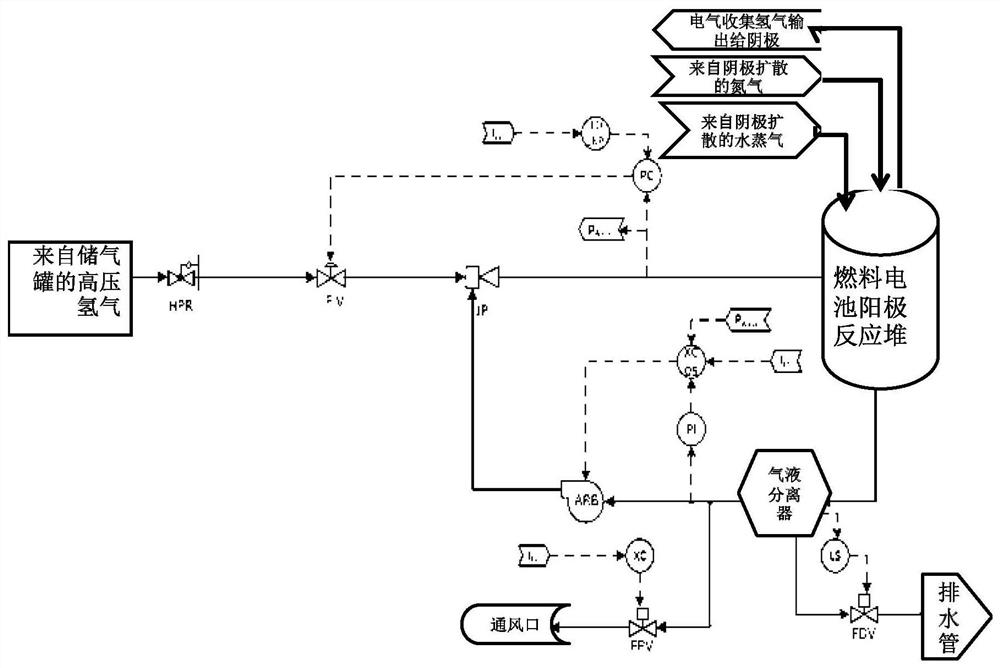
[0042] This embodiment relates to a method for controlling a drain valve of a fuel cell gas-liquid separator. In this embodiment, the fuel cell is a hydrogen-oxygen fuel cell.

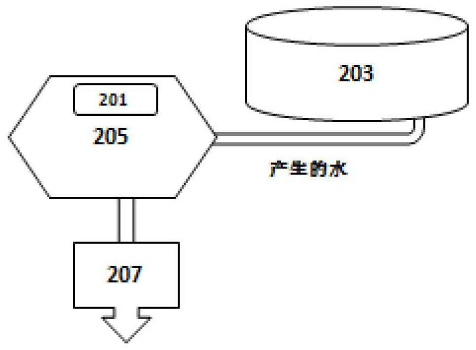
[0043] see figure 1 , which is a schematic diagram of the fuel cell structure; in addition, see figure 2 , which enlargedly shows the control mode and structure of the drain valve 207 of the gas-liquid separator 205 . It can be seen that during the working process of the fuel cell, the anode reactor will produce water, so a water outlet is provided on the side of the anode reactor, and the water generated by the reaction is transported to the gas-liquid separator 205 through the water pipeline. The function of the gas-liquid separator 205 is gas-liquid separation, that is, to separate water and hydrogen. The water is discharged through the drain valve 207 below, and the hydrogen is recycled for reuse.

[0044] As described in the background art, in the structure of the above-mentioned prior art, i...

no. 2 example

[0055] This embodiment relates to a method for controlling a drain valve of a hydrogen-oxygen fuel cell gas-liquid separator for automobiles and a control device for the drain valve of the fuel cell gas-liquid separator.

[0056] As described in the background and see figure 2 As shown, the fuel cell gas-liquid separator drain valve control method and control device in the prior art, wherein 201 is a water level sensor.

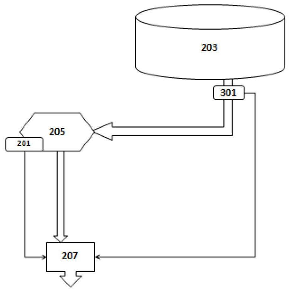
[0057] Figure 3B A control method and a control device of a gas-liquid separator drain valve (FDV) according to another embodiment of the present disclosure are shown.

[0058] Such as Figure 3B As shown, according to the exemplary embodiment of the present disclosure, the air pressure sensor 301 may also be disposed in the downstream part of the gas passage of the gas-liquid separator to detect the gas pressure drop rate.

[0059] see figure 1 and Figure 3B , in the method of this embodiment, it also includes detecting the state of the fuel cell exh...


PUM


Abstract

The invention provides a control method for a drain valve of a gas-liquid separator of a fuel cell. The control method comprises the following steps: detecting the gas state of process gas for the fuel cell below the gas-liquid separator; and controlling the on-off state of a drain valve of the gas-liquid separator according to the detection result of the gas state. The invention also provides a control device for the drain valve of the gas-liquid separator of the fuel cell. The control device comprises: a detection module which is used for detecting the gas state of the process gas for the fuel cell below the gas-liquid separator and outputting a detection result; and a drain valve switch module which is used for receiving the detection result of the gas state and opening and closing a drain valve according to the detection result. The invention also relates to the fuel cell. The fuel cell comprises: the gas-liquid separator disposed at the downstream of the anode reactor of the fuel cell and capable of receiving and storing water generated by the anode reactor; and a gas-liquid separator drain valve arranged below the gas-liquid separator and used for discharging water stored in the gas-liquid separator.

Description

technical field [0001] The present disclosure relates to a fuel cell for vehicles and a vehicle with the fuel cell, in particular to a control method and a control device for a gas-liquid separator drain valve of the fuel cell. Background technique [0002] A fuel cell is a chemical device that directly converts the chemical energy of fuel into electrical energy, also known as an electrochemical generator. Fuel cells are the fourth power generation technology after hydroelectric power, thermal power and atomic power. Generally, hydrogen, carbon, methanol, borohydride, coal gas or natural gas are used as fuels as anode / cathode, and oxygen in the air is used as cathode / cathode. anode. The main difference between it and the general battery is that the active material of the general battery is pre-placed inside the battery, so the battery capacity depends on the amount of the active material, while the active material of the fuel cell is continuously supplied while reacting, so...

Claims


Application Information

Patent Timeline
Patent Type & Authority Applications(China)
IPC IPC(8): H01M8/04291H01M8/0438H01M8/04955
CPCH01M8/04291H01M8/04432H01M8/04955H01M2250/20Y02E60/50
Inventor 杜文帅A·瓦萨帕那瓦拉崔天宇
Owner FTXT ENERGY TECH CO LTD
Why Eureka
Try Eureka