
Deformation analyzer of barrel body

A technology of measuring device and cylindrical body, applied in the direction of measuring device, optical device, bearing of rotating motion, etc., can solve the problems of inability to perform stability and reliability, increase of measurement error, time-consuming and troublesome, etc.

Inactive Publication Date: 2004-12-01
MINEBEA CO LTD
View PDF0 Cites 0 Cited by
  • Summary
  • Abstract
  • Description
  • Claims
  • Application Information

AI Technical Summary

Problems solved by technology

[0005] First, with mechanical contact, especially in cylindrical bodies C such as small inner rings Ci with an outer diameter of several mm or less, measurement errors become large, and reproducible, high-precision measurements cannot be performed.
[0006] Second, since the main work has to be done manually by the operator, the measurement is time-consuming and troublesome, and it cannot be measured with high stability and reliability.

Method used


Image

  • Deformation analyzer of barrel body
  • Deformation analyzer of barrel body
  • Deformation analyzer of barrel body

Examples


Embodiment Construction

[0018] Preferred embodiments of the present invention will be described in detail below with reference to the accompanying drawings. The accompanying drawings do not limit the present invention, but are intended to make the present invention easy to understand. In addition, detailed descriptions of well-known parts are omitted in order not to obscure the invention.

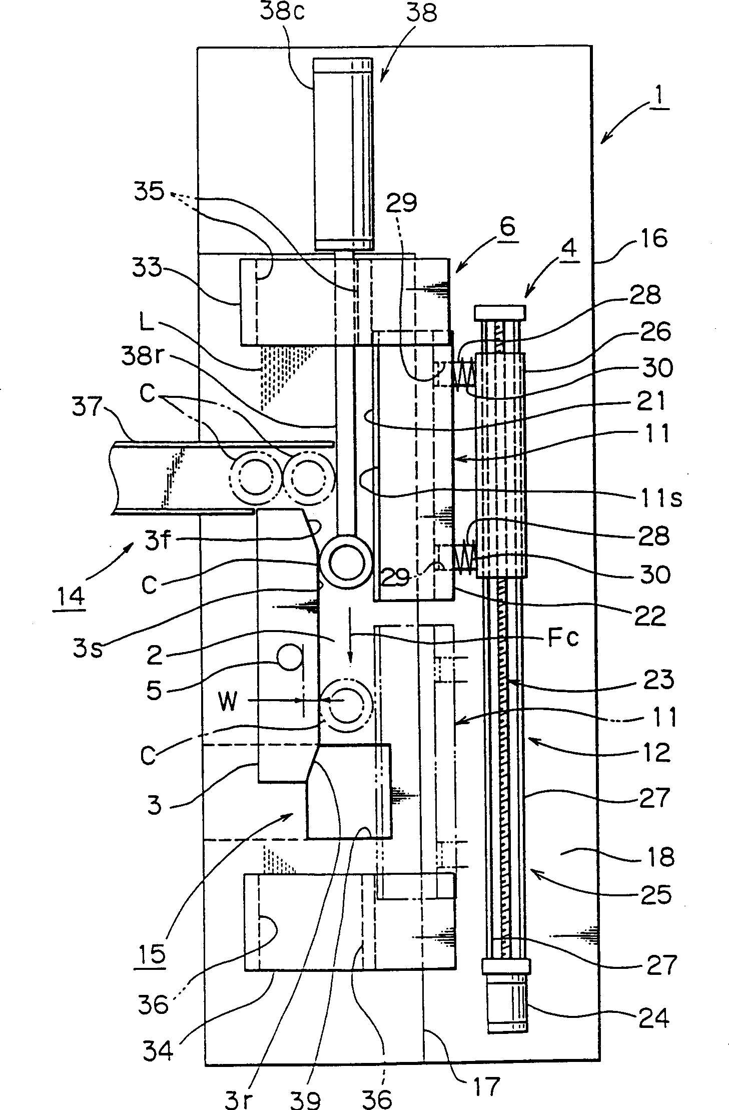
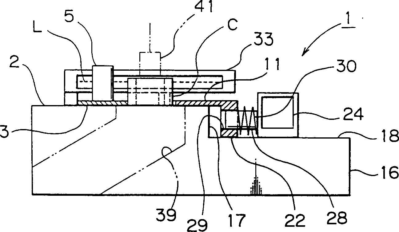
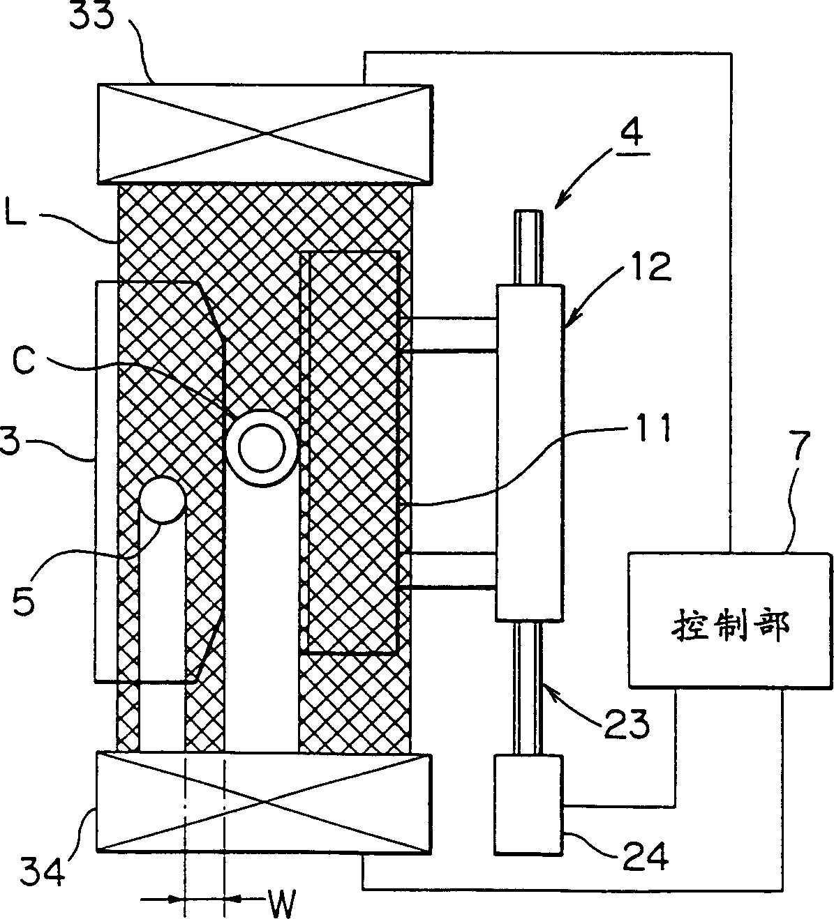
[0019] First, refer to Figure 1-Figure 4 The configuration of the strain measuring device 1 of this embodiment will be described.

[0020] In the figure, symbol 16 is a base on which a flat surface 2 is formed. At the middle position of the flat surface 2, a fixed linear guide part 3 is fixedly provided. The fixed linear guide part 3 is formed of a guide member having a certain thickness, and at least one side is formed with a linear side part 3s having a length such that the cylindrical body C as the object to be measured can be turned more than one turn. The linear side portion 3s ensures a high degree of l...


PUM


Abstract

An apparatus for measuring distortion of a cylindrical body includes: a stationary straight rail provided on a flat surface; a cylindrical-body transfer mechanism for rolling the cylindrical body such that a peripheral surface of one end of the cylindrical body remains in contact with the stationary straight rail; a reference pole disposed at a position separated a predetermined distance from the cylindrical body in a direction perpendicular to the rolling direction of the cylindrical body; a laser scan micrometer capable of simultaneously scanning the top end of the cylindrical body and the reference pole by means of laser beam projected toward the rolling direction to thereby measure a distance between the cylindrical body and the reference pole; and a control section for processing measurement data so as to obtain radial distortion of the cylindrical body.

Description

technical field [0001] The present invention relates to a deformation amount measuring device of a cylindrical body suitable for use when measuring the radial deformation strain amount of a cylindrical body such as an inner ring and an outer ring of a bearing. Background technique [0002] Generally, when there is deformation in the radial direction of the inner ring Ci and the outer ring Co of the ball bearing M as shown in FIG. Vibration in the axial direction and the like cannot provide smooth and stable rotational performance. Therefore, it is required to reduce the deformation of the inner ring Ci and outer ring Co as much as possible. That is, when the position where the lower end surface Cid of the inner ring Ci is fixed is rotated once, the radial deformation amount Ed of the upper end surface Ciu of the inner ring Ci is ideally zero, but in reality there is deformation, and it is required to make the deformation The quantity Ed is within specified tolerances. [0...

Claims


Application Information

Patent Timeline
Patent Type & Authority Patents(China)
IPC IPC(8): G01B11/16F16C19/52G01B11/08G01N21/952
CPCG01B11/08
Inventor 坂口岩竹重义夫
Owner MINEBEA CO LTD
Learn More