Bender for bending material, such as tube, rod section and/or metal wire rod

A metal wire, bending tube technology, applied in the field of bending machines, can solve the problems of precise dismantling and accurate positioning of difficult-to-bend parts

Inactive Publication Date: 2005-01-19
BLM
View PDF1 Cites 5 Cited by
  • Summary
  • Abstract
  • Description
  • Claims
  • Application Information

AI Technical Summary

Problems solved by technology

[0009] Another disadvantage of existing bending heads is that it is difficult to carry out precise dismantling and accurate positioning of bent parts without damaging the bent parts at the end of the bending

Method used


Image

  • Bender for bending material, such as tube, rod section and/or metal wire rod
  • Bender for bending material, such as tube, rod section and/or metal wire rod
  • Bender for bending material, such as tube, rod section and/or metal wire rod

Examples


Embodiment Construction

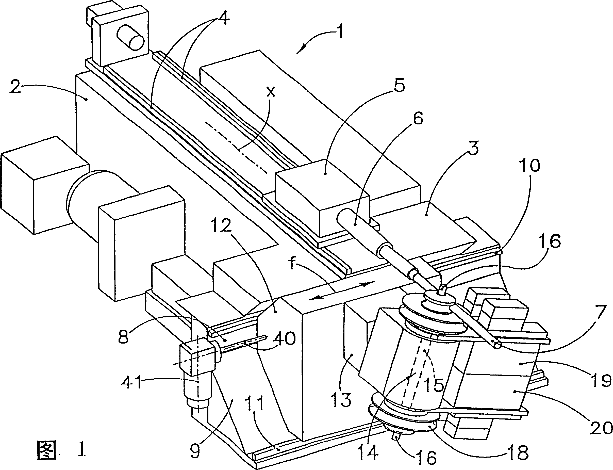
[0021] As shown in FIG. 1 , the bending machine, generally designated 1 , is equipped with a T-shaped machine comprising a longitudinal section 2 and a cross piece 3 forming the front end of the bending machine 1 .

[0022] On its top face, the machine tool is equipped with precisely parallel rail mechanisms 4, on which a known bracket 5 is movably supported, which includes a Indicates) pipe clamp 6 that rotates.

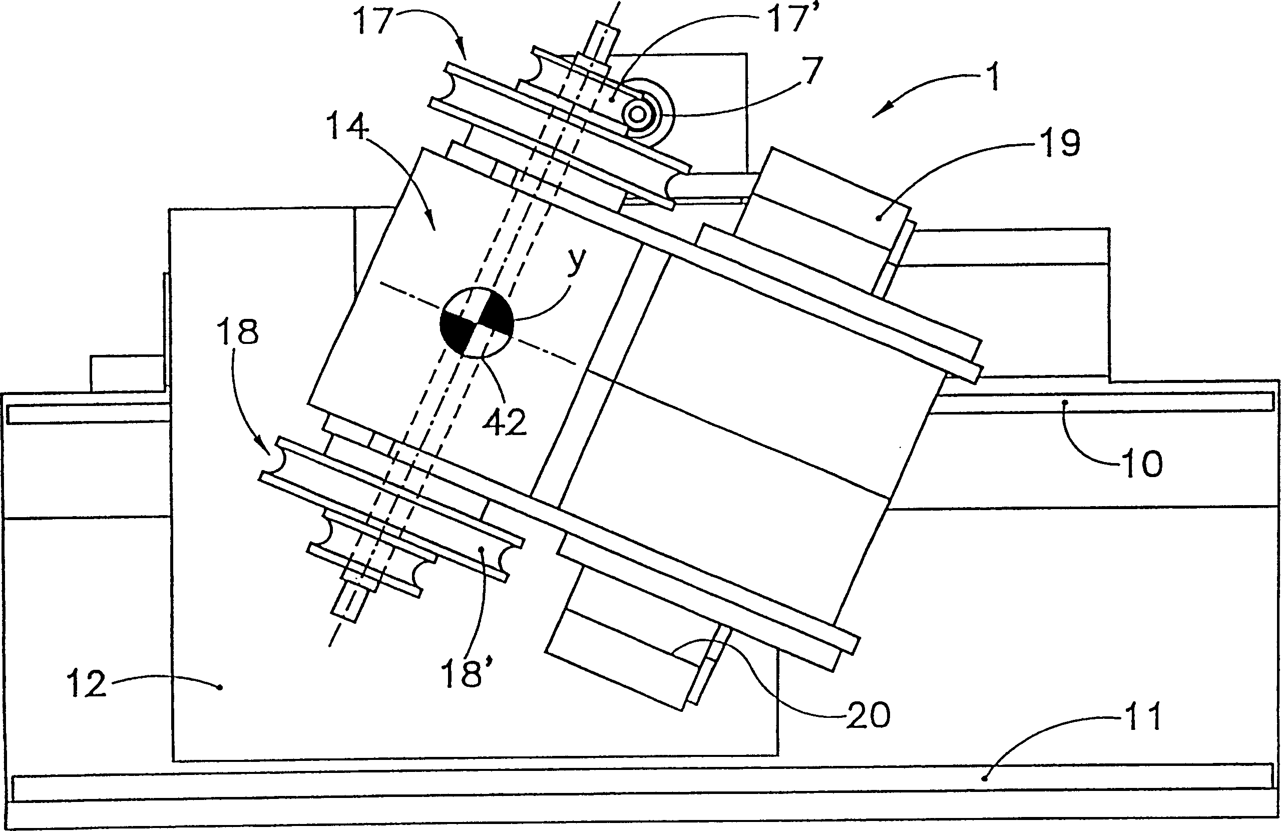
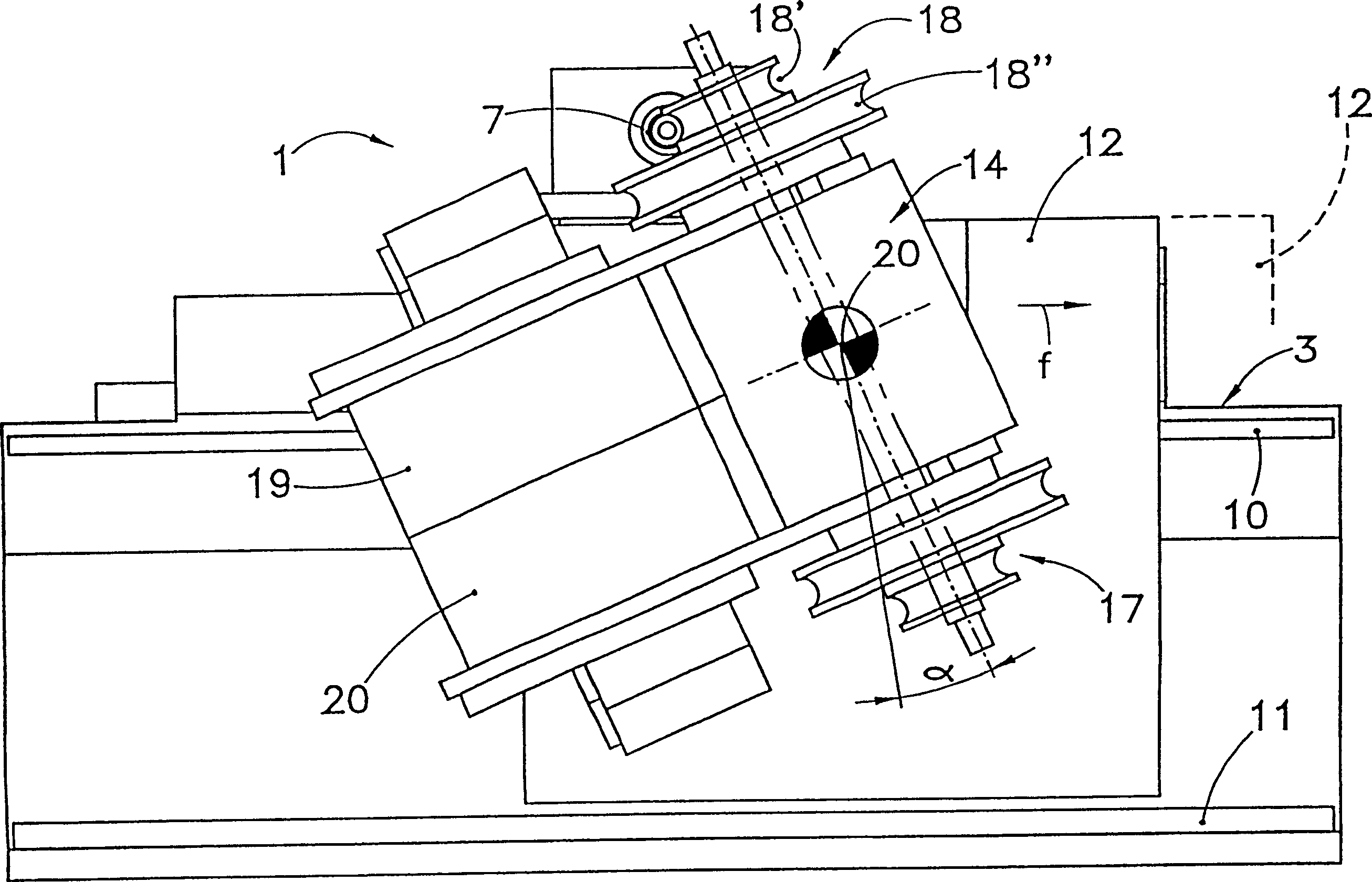
[0023] On its front side, the cross piece 3 is equipped with a vertical wall 8 which intersects an oblique forward wall 9 which supports a precision guide boss 10 and which is provided at the end of the oblique wall 9 Another precision guide boss 11 is provided.

[0024] In the cavity defined by the walls 8, 9, a prismatic support 12 is arranged.

[0025] On its top side, the bracket 12 rests on the precision guide boss 10 , while on its bottom side it rests on the precision guide boss 11 .

[0026] For example by means of a ball recirculating screw 40 and a cont...


PUM


Abstract

A bender for tube, rod, shaped wire, or metal wire has a T-shaped machine-tool body with parallel guide bosses the support a driven movable supporter, a parallel guide track mechanism for supporting a movable supporter to feed or rotate the tubular material to position it at a pre-defined position, a bending head equipped to said supporter on bosses, bending module and swinging bending arm. The said bending head is supported by a horizontal axle and can be rotary around the horizontal axle under control.

Description

technical field [0001] The present invention relates to bending machines for bending linear materials such as tubes, rods, profiles or metal wires. Background technique [0002] In the prior art, as described in US patent application US5946960A, in order to bend tubes, rods, profiles or wires, bending machines were used which included a machine tool into which the front end of the tube to be bent was fed. For the controllable feeding of the pipe, a movable support is used which is controllably driven along the parallel guide rail mechanism of the machine tool. The vertical axis rotates. [0003] On the front end of existing pipe benders, there are provided a number of overlapping bending dies that can be placed as desired on the pipe to be bent, thereby allowing the known swinging bending arm to perform a radius bend on the pipe front end. Bending work that is different from bending shape. [0004] Modern bending machines usually include a cutting mechanism on their front...

Claims


Application Information

Patent Timeline
Patent Type & Authority Patents(China)
IPC IPC(8): B21D7/025B21D7/024
CPCB21D7/024
Inventor M·布罗吉M·比拉
Owner BLM
Why Eureka
Try Eureka