Reel housing for connection line

A technology for connecting wires and reels, which is applied in the field of reel casings, can solve problems such as reel falling off, and achieve effective use

Inactive Publication Date: 2005-01-19
TANAKA DENSHI KOGYO KK
View PDF2 Cites 0 Cited by
  • Summary
  • Abstract
  • Description
  • Claims
  • Application Information

AI Technical Summary

Problems solved by technology

[0010] In addition, in the existing reel cover, as mentioned above, the contact pressure of the reel holding part is adjusted by the opening and closing operation of the fing

Method used


Image

  • Reel housing for connection line
  • Reel housing for connection line
  • Reel housing for connection line

Examples


Embodiment 1

[0050] Embodiment 1: refer to figure 1 -4

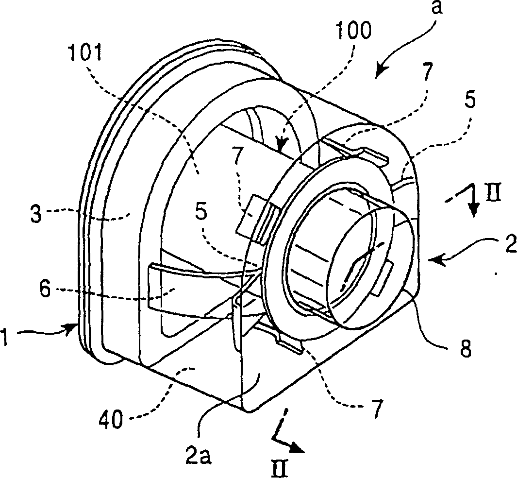
[0051] figure 1 In -4, a is a reel cover, 100 is a reel, 110 is an electric wire, 200 is a reel holder of a wire bonding device, and 300 is a reel locking device attached to the holder.

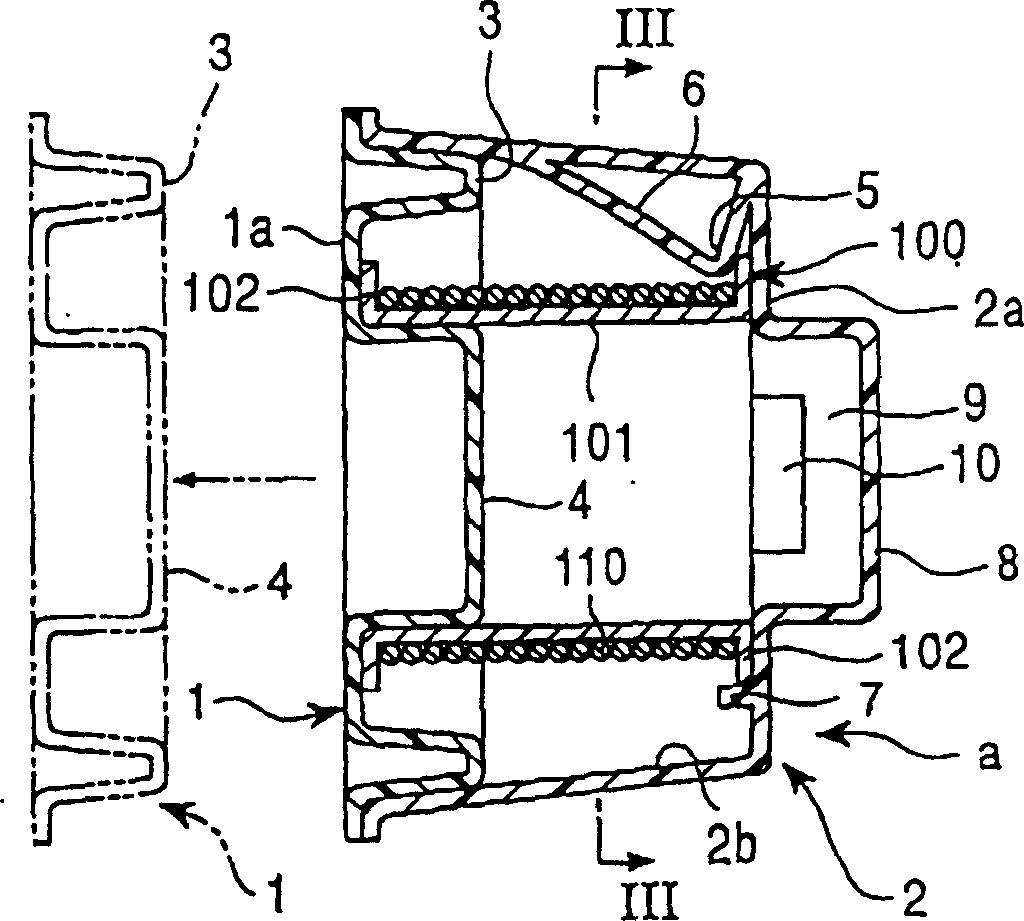
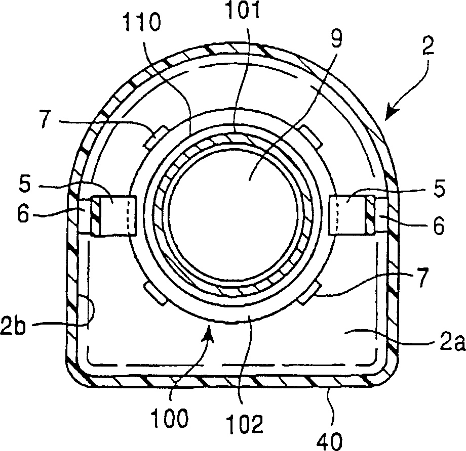
[0052] The reel 100 has a structure commonly used in this technical field, and is provided with a cylindrical body 101 around which an electric wire 110 is wound, and left and right flanges 102, 102 provided on opening edges at both ends of the reel 100 .

[0053] The reel housing a is composed of a base plate 1 and a cover body 2 that are fitted together. The base plate 1 and the cover body 2 are made of materials such as plastics, and are elastically deformable by vacuum forming. The electric wire reel 100 is integrally formed by the top-covering fitting cover 2 .

[0054] The outer peripheral edge of the base plate 1 is protruded with an outer peripheral bulge 3 that can be fitted with the cover body 2, and the central part of the side wall 1a...

Embodiment 2

[0069] Embodiment 2: refer to Figure 5-1 0

[0070] Figure 5-1 The reel cover a' shown in 0 is composed of a base plate 1' and a cover 2' that are fitted together. The roll 100 inside the cover 2' is instead held by the base plate 1'.

[0071] In the figure, the components common to Embodiment 1 are represented by the same symbols as those of Embodiment 1. These common components will not be described repeatedly, and only the parts different from Embodiment 1 will be described as follows.

[0072] On the surface (i.e., the outer surface) 1b on the outer side of the housing corresponding to the side wall 1a of the base plate 1', there are a plurality of places that can be elastically engaged with the outer periphery of the flange 102 for maintaining the engagement of the flange 102. Sheet 11.

[0073] These engaging pieces 11 are mounted on a plurality of places on the outer surface 1b of the base plate 1 ′, and the front end of the mounting portion 12 is bent in a roughl...

Embodiment 3

[0087] Embodiment 3: Refer to Figures 11-17

[0088] The reel case a" shown in FIGS. 11-17 is composed of the substrate 3 and the cover 4 which are fitted together as shown in FIGS. 11-13, and accommodates the reel 2 with the electric wire 1 wound therein.

[0089] The drum 2 has flanges 2b, 2c at both ends. The diameter of the flanges 2b, 2c is in the range of 58.5-80mm.

[0090] The reel case a" is composed of a base plate 3 and a cover body 4 which are fitted together. The base plate 3 and the cover body 4 are made of materials such as plastics and are elastically deformable by vacuum forming. After holding the spool 2 wound with the electric wire, the cover body 4 is fitted in such a way as to cover the side to make it integral.

[0091] The outer peripheral portion of the base plate 3 is provided with an outer peripheral bulge 5 that can be fitted with the opening edge 4a of the cover body 4, and a central portion surrounded by the outer peripheral bulge 5 is formed wit...


PUM

PropertyMeasurementUnit
Diameteraaaaaaaaaa

Abstract

A reel housing for a connection line is characterised in that at least one of a substrate or a lid body is provided with a detachable elastic clamping slice at a periphery outside a flange of a reel and holds the reel winded with wires in the reel housing. The holding state is maintained except the clamping slice is elastically distorted so that the clamping is released. And because the holding state is realized by clamping the clamping slice with the periphery outside the flange, the wires winded on the reel body or an inner side of the reel body would not be disturbed.

Description

technical field [0001] The present invention relates to a spool case for a semiconductor bonding wire, and more specifically, to a spool case that can handle a spool without touching the bonding wire wound on the spool with hands. reel cover. Background technique [0002] Conventionally, there are known various housings for accommodating a reel wound with connecting wires for assembling semiconductor devices. [0003] For example, Japanese Publication No. 58-41188 discloses a base plate with an upwardly bulging fitting ridge that can be fitted by a reel and a cover body that can be fitted into the outer peripheral bulge of the base plate. Formed on the body is a concave portion corresponding to the above-mentioned fitting bulge for fitting the reel, and a reel cover that presses the accommodated reel to prevent it from loosening by means of the above-mentioned fitting bulge and the cover body. [0004] However, the reel housed in such a reel case needs to be taken out from...

Claims


Application Information

Patent Timeline
IPC IPC(8): H01L21/60B21C47/28B23K20/00B65D85/04B65H49/38B65H67/06B65H75/14
CPCH01L2224/851B65H2701/361B21C47/28H01L2924/01002H01L2924/01005H01L24/78B65H67/065B65H2402/414H01L2924/01082H01L2224/786B65D85/04B65H49/38H01L2924/01029H01L2924/01004B23K20/004H01L2924/01006H01L2924/01033B65H75/141H01L2924/00014H01L2224/451H01L2224/48H01L2924/00H01L2224/45099H01L21/60
Inventor 安助忠雄佐藤修梶淑男西村启一
Owner TANAKA DENSHI KOGYO KK
Why Eureka
Try Eureka