CT machine

A rack and servo motor technology, applied in medical science, equipment for radiological diagnosis, diagnosis, etc., can solve the problems of expanding the irradiation area, harming the human body, increasing the radiation amount, etc., to reduce the radiation energy, adjust the speed quickly, image clarity effect

Inactive Publication Date: 2005-02-16
PHILIPS CHINA INVESTMENT +1
View PDF0 Cites 0 Cited by
  • Summary
  • Abstract
  • Description
  • Claims
  • Application Information

AI Technical Summary

Problems solved by technology

In the application, it is felt that the fan angle, fan beam center, and fan beam width of the rays emitted by the ray element in this CT machine cannot be changed with the change of the subject's body shape or can only change the fan beam width, so there is an expansion Irradiate the surface, increase the amount of radiation, and cause certain harm to the human body

Method used


Image

  • CT machine
  • CT machine
  • CT machine

Examples


Embodiment Construction

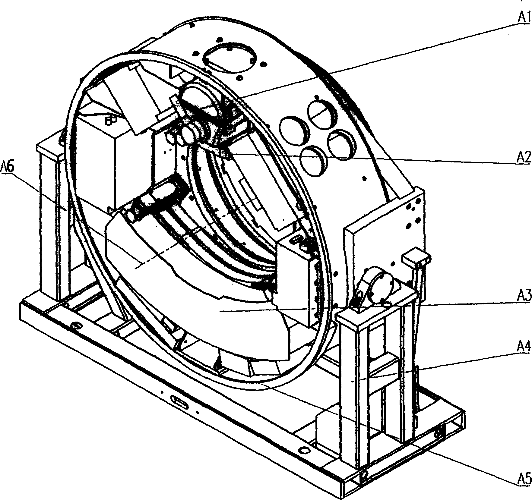
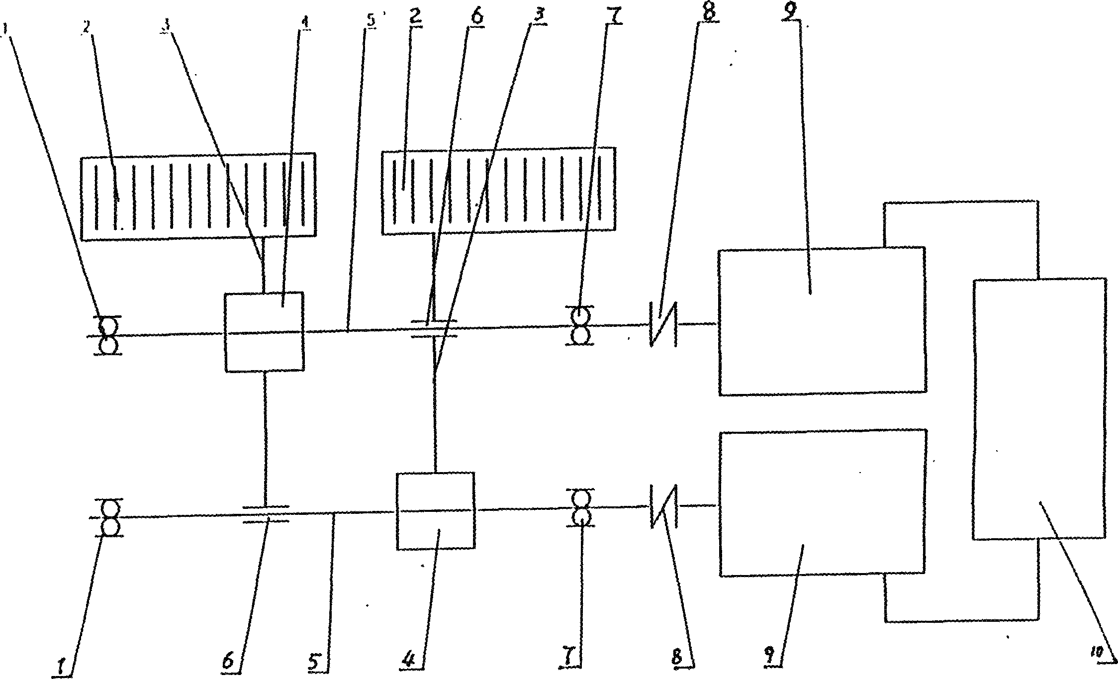
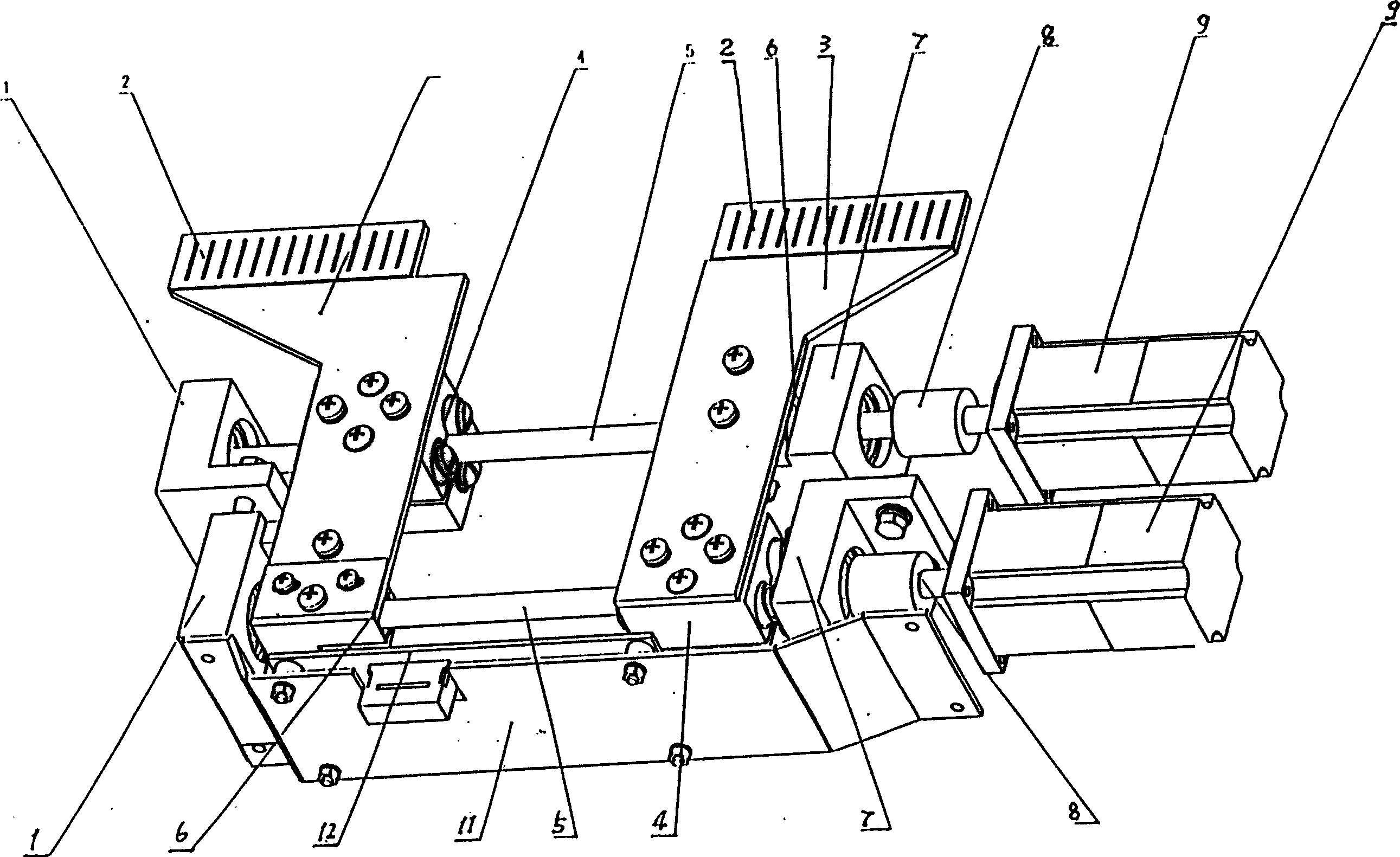
[0014] Depend on Figure 1-6 It can be known that a CT machine is based on the existing CT machine including the frame, the detection device, the rotating plate, the rotating shaft and the radioactive source, and is provided with a workable beam limiter that can rotate around the system axis under the radioactive source. , the beam limiter includes a control device and a mechanical transmission mechanism controlled by it, wherein the control device includes: a servo controller, a servo, a servo motor, a position detector, an incremental encoder, an angle encoder and a zero position Signal, among which the servo controller contains XC2S150 type digital circuit with large-scale programmable logic function and its matching DM74ALS245, SN74LS540 type has bus buffer digital circuit, XC18V02 type has digital circuit with logic storage function, 26LS31 type has differential transmission function Digital circuit, TLP521-1, TLP521-4 digital circuit with optocoupler function, at the sam...


PUM


Abstract

A CT machine is composed of radioactive source, detector system, machine frame, rotary plate and rotary axle, and is characterized by its additional intelligent beam limiter for regualting the central position and width of sectorial ray beam. Said beam limiter consists of the intelligent controller composed of servo controller, servo unit, servo motor, position detector, angle encoder, and zero-position signalling unit, and the mechanical transmission mechanism. Its advantages are low radiant energy, high scan speed and high clearness of image.

Description

Technical field [0001] The invention relates to medical equipment, in particular to CT machine equipment for non-destructive detection of human diseases. Background technique [0002] Currently commercially available CT machines are mainly composed of radioactive sources, detectors, DAS system imaging systems, display systems, beds and rotating parts, wherein: radioactive sources and detection systems are installed on racks that can rotate around the axis, and The supporting device is installed in the bed and can move along the axis of the system. When the radiation beam from the radiation source passes through the subject and reaches the detector, a signal is generated, which is converted by the DAS system and input to the imaging system. Create a layered two-dimensional cross-sectional image. In the application, it is felt that the fan angle, fan beam center, and fan beam width of the rays emitted by the ray element in this CT machine cannot be changed with the change of ...

Claims


Application Information

Patent Timeline
Patent Type & Authority Patents(China)
IPC IPC(8): A61B6/02
Inventor 台谨贤楼珊珊相欣祝建华
Owner PHILIPS CHINA INVESTMENT
Why Eureka
Try Eureka