Doorstop

A technology of door brakes and brakes, which is applied to doors, manufacturing tools, multi-purpose hand tools, etc., can solve the problems of increasing the tolerance chain and door brake structure volume, high cost, complex structure and functions, etc., to ensure the strength and High stability, light weight, high strength and high stability effect

Inactive Publication Date: 2005-03-16
EDSCHA ENG GMBH
View PDF3 Cites 0 Cited by
  • Summary
  • Abstract
  • Description
  • Claims
  • Application Information

AI Technical Summary

Problems solved by technology

[0003] The necessity of providing separate bearing and / or holding elements and guide shoes increases the overall volume of the tolerance chain of the cooperating functional parts and the door brake
In addition, its structure and function become complicated and costly

Method used


Image

  • Doorstop
  • Doorstop
  • Doorstop

Examples


Embodiment Construction

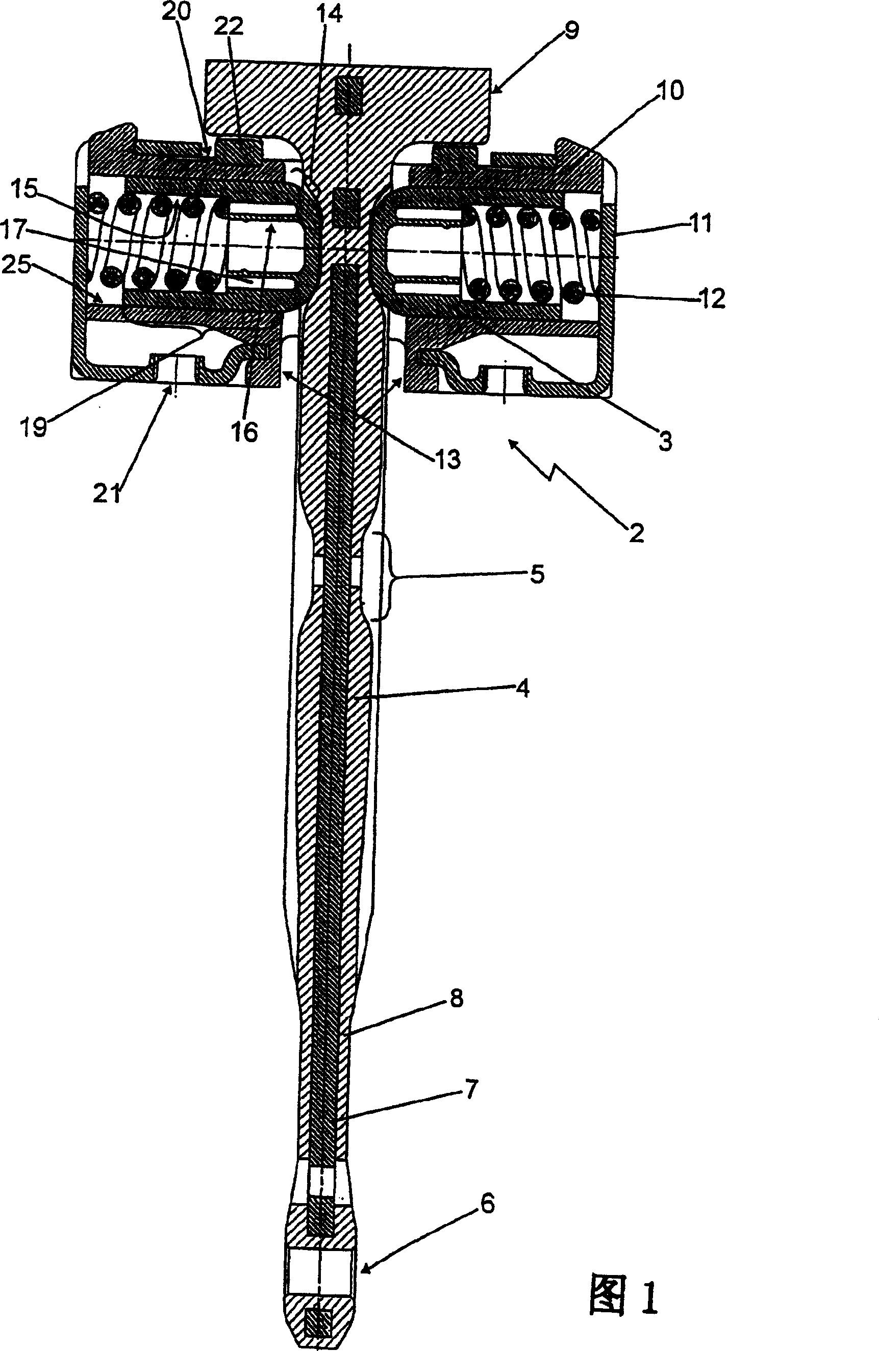
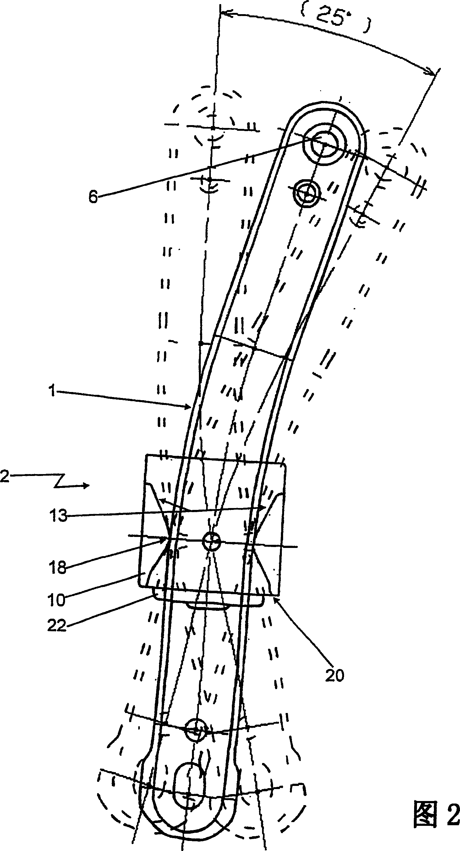
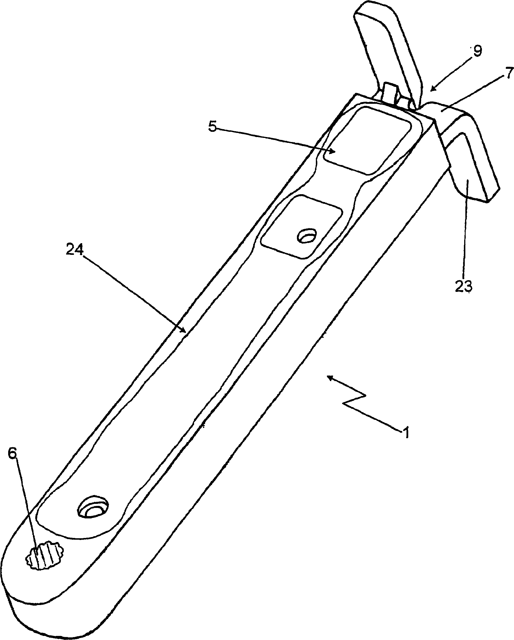
[0039]FIG. 1 shows a side sectional view of a door stopper according to the invention, wherein the section of the door stopper is parallel to the hinge axis and the door holding rod 1 passes through the holding part 2 . The door holding rod 1 has a bearing eye 6 at its lower end in the figure and a support 9 at the other end. The door retaining rod 1 consists of a metal core 7 , for example a flat steel section, which is encapsulated with plastic. The plastic shell 8 has different thicknesses along its length and forms raised portions in the form of local thickenings which form the braking ramps 4 and the locking recesses 5 between the raised portions. In the illustrated embodiment the abutment 9 is integrally T-shaped, which abutment constitutes an end stop corresponding to the open position of the door. Alternatively, the abutment 9 or the end stop can also be formed by a peg, which is inserted in the door holding rod 1 via a corresponding hole in the direction of the hinge...


PUM


Abstract

A doorstop that includes a retainer piece disposed on one of a door and a door support, the retainer piece including a plastic housing with a main opening and a guide opening arranged perpendicular to the main opening and parallel to a pivot axis of the door. The doorstop also includes a door retaining rod articulated on the other of the door and the door support. The door retaining rod passes through the main opening of the retainer piece housing and includes a brake ramp and a catch depression on a side of the door retaining rod. The doorstop also includes a catch device configured to determine specific door opening positions. The catch device includes a brake body and a spring. The catch device connects the retainer piece and the door retaining rod to each other in a moveable manner. The brake body includes a hollow cylinder having a semi-spherical closed end and an open end and is slidingly disposed in the guide opening of the retainer piece. The open end accommodates the spring so that the closed end is pre-tensioned by the spring relative to the brake ramp and catch depression and is guided in the guide opening free of tilt.

Description

technical field [0001] The invention relates to a door brake, in particular for a motor vehicle, comprising: a door retaining rod hinged to a door structure, door or door post, the door retaining rod being parallel to the door hinge; a fixed A retaining element on another door structure, wherein the retaining element and the door retaining rod passing through the retaining element are connected to each other movably relative to each other by a locking device, and wherein the locking device determines the open position of the door and There are braking and holding bodies, which are mounted in the holding part so as to be movable against a spring load relative to the door holding lever and are preloaded on braking ramps and locking recesses, which And a locking recess is provided on at least one side of the door holding rod in a transverse direction with respect to the direction of movement. Background technique [0002] Such door brakes are known from the prior art, for exam...

Claims


Application Information

Patent Timeline
Patent Type & Authority Patents(China)
IPC IPC(8): E05C17/22B60J5/04E05C17/20
CPCY10S292/15E05C17/203
Inventor 彼得·霍夫曼贡多尔夫·海因里希斯拉尔夫·杜宁
Owner EDSCHA ENG GMBH
Why Eureka
Try Eureka