Vibrating trigger button

Active Publication Date: 2010-08-05
JANAM TECH
View PDF10 Cites 4 Cited by
  • Summary
  • Abstract
  • Description
  • Claims
  • Application Information

AI Technical Summary

Benefits of technology

[0012]It is another object of the invention to provide, for a hand-held device, a vibration alert which is capable of making efficient use of battery power.
[0013]It is a further object of the invention to provide a vibration alert which may be felt by the user even when low amplitude vibrations are emitted by the motor.
[0016]It is also an object of the invention to provide a vibration alert system which may be light-weight and compact.SUMMARY OF THE INVENTION
[0020]The motor's body may contact one side of the printed circuit board, and directly on the opposite side of the board may be a platform with a post extending therefrom to support one end of a coil spring, with the other end being retained within the device. When the user completes an operation, the device may signal the printed circuit board, which causes a counterweight to rotate and transmit vibrations to the trigger switch. The counterweight may create vibrations below, at, or near the natural resonance frequency of the spring-mass system. The arrangement may also be damped with a foam pad in order to quickly eliminate vibrations cause by the motor after the alert is to end, as the counterweight of the motor slowly spins to a static condition. This damping may permit a more discrete time period for delivery of a vibratory alert.

Problems solved by technology

When the user completes an operation, the device may signal the printed circuit board, which causes a counterweight to rotate and transmit vibrations to the trigger switch.

Method used


Image

  • Vibrating trigger button
  • Vibrating trigger button
  • Vibrating trigger button

Examples


Embodiment Construction

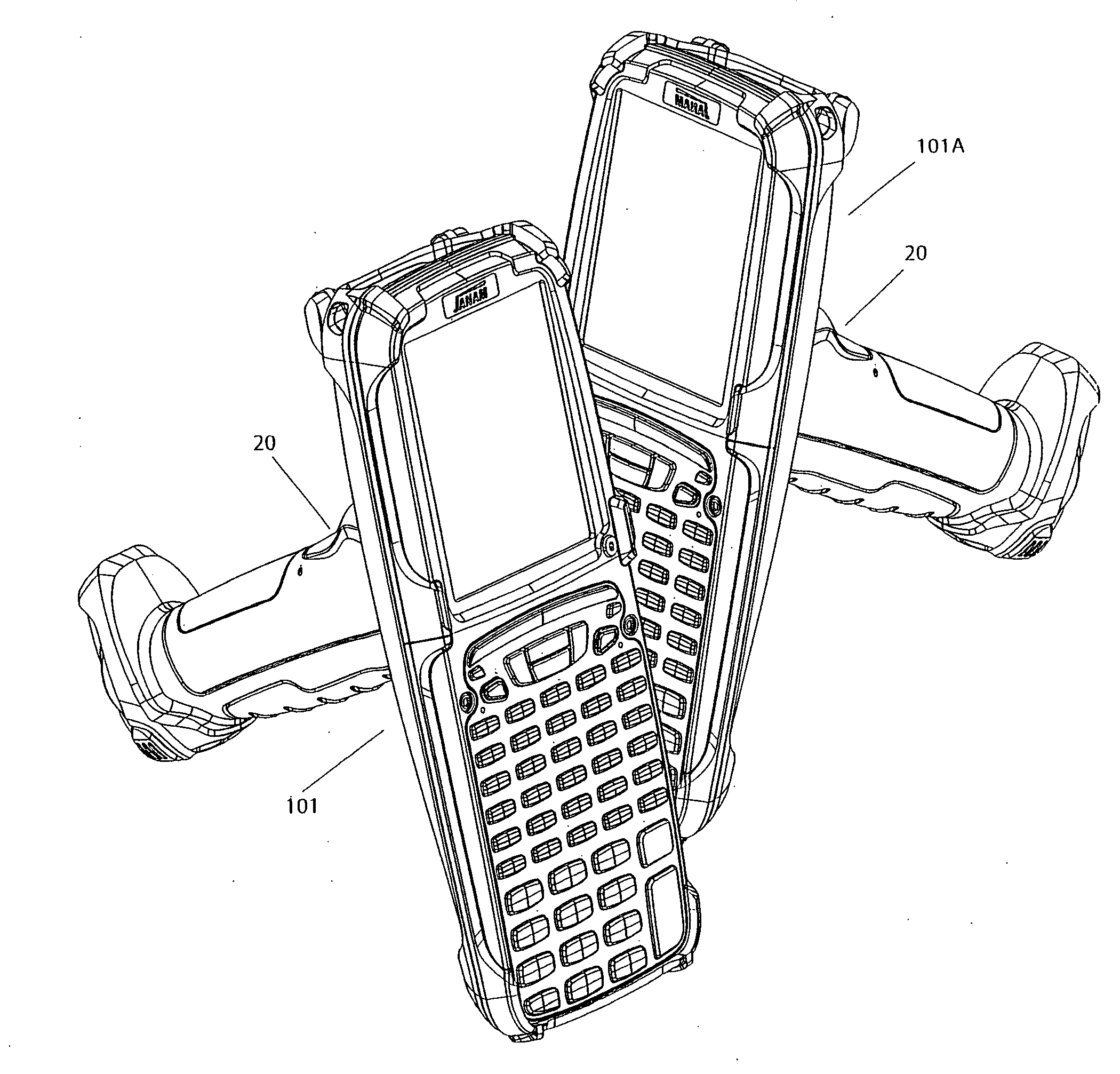
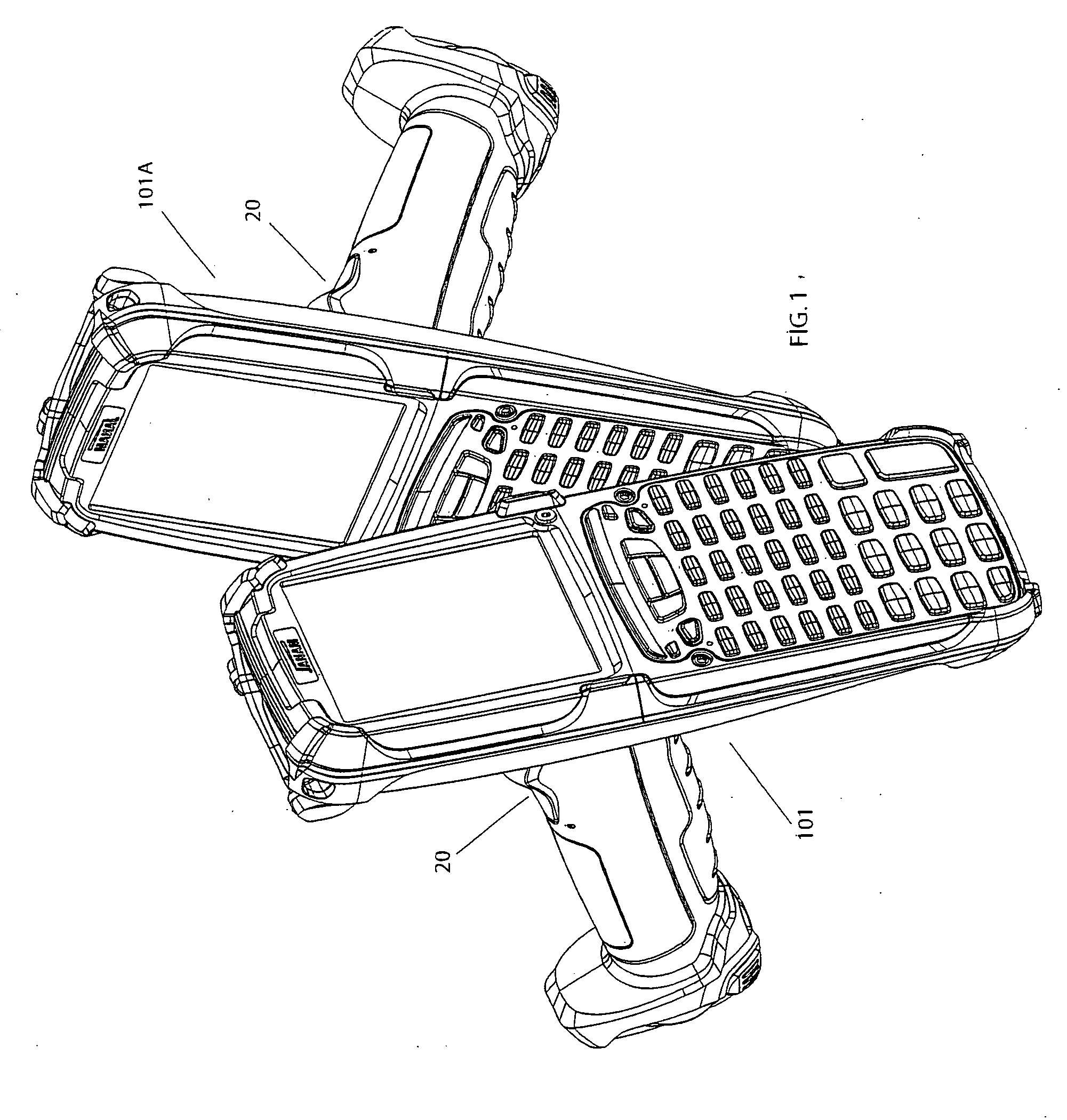
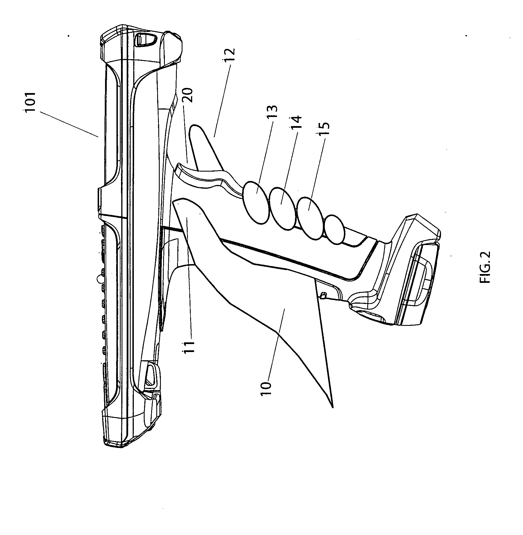
[0035]FIG. 1 shows a pair of gun-shaped mobile computing devices 101 and 101A merely to be illustrative of the kinds of hand-held electronic devices which may incorporate the trigger assembly 20 of the current invention. The trigger assembly 20 is shown incorporated into such a device and with a user's hand grasping the device in the side view of FIG. 2. The trigger assembly 20 may extend along the handle 102 of the device 101 so that an index finger 12 and middle finger 13 may contact the button and be able to directly receive tactile alerts in the form of vibrations from the trigger assembly 20. The trigger may be extended so that all four finger of the user contact the trigger to directly be exposed to vibrations. The gripping regions for the index finger 12 and middle finger 13 are more visible in the enlarged views of FIGS. 3 and 4.

[0036]As seen in the perspective views in FIGS. 5 and 6, the trigger assembly 20 may be comprised of a housing 50. The housing 50 may be formed of a...


PUM


Abstract

A trigger switch for a hand-held device provides vibrating alerts directly to one or more fingers of a user's hand when signaled by the device. The trigger switch housing is pivotally mounted in the device with a stop to limit outward travel therefrom. A housing cavity receives a miniaturized vibrating motor that is electrically coupled to a printed circuit board, which has a wire bundle with a connector to couple the board to the device. The motor's body may contact one side of the printed circuit board, and directly on the opposite side of the board may be a platform with a post extending therefrom to support one end of a coil spring, with the other end being retained within the device. When the user completes an operation, the device may signal the printed circuit board, which causes a counterweight to rotate and transmit vibrations to the trigger switch.

Description

[0001]This application claims priority on U.S. Provisional Application Ser. No. 61 / 203,411 filed on Dec. 23, 2008, the disclosures of which are incorporated herein by reference.FIELD OF THE INVENTION[0002]The present invention relates to improvements in feedback alerts to users of mobile devices, and more particularly to a vibration alert which is more effective while reducing power consumption, weight and cost.BACKGROUND OF THE INVENTION[0003]There are now, and have in the past, been many electronic devices which seek to interact and communicate with a user in one form or another. One of the oldest examples may be the Morse code signals transmitted by the electric telegraph around 1840, which originally marked indentations on a paper tape that needed to be translated, but the operators soon learned to directly translate the message from the clicking noises made by the receiver's armature. It was Alexander Graham Bell's experiments with a harmonic telegraph which sought to transmit ...

Claims


Application Information

Patent Timeline
IPC IPC(8): H04B3/36
CPCG06F3/016
Inventor LERNER, HARRY B.CHO, THAN CHO
Owner JANAM TECH
Why Eureka
Try Eureka