Claw-pole type singel-phase motor, claw-pole type single-phase motor system and electric pump, electric fan and vehicle provided with claw-pole type single-phase motor

a single-phase motor and claw-pole technology, applied in the field of claw-pole type motors, can solve the problems of insufficient axis length, low material utilization, and inability to achieve cost reduction

Inactive Publication Date: 2008-01-24
HITACHI IND EQUIP SYST CO LTD +2
View PDF6 Cites 14 Cited by
  • Summary
  • Abstract
  • Description
  • Claims
  • Application Information

AI Technical Summary

Benefits of technology

[0010] The engine room, where those devices are stored, is a space crowded with various types of parts. In particular, a significant increase in the number of mounted parts for implementing recent advances in the hybrid system and the sophisticated functions requires that the parts stored therein be more light-weight and compact than those stored in other rooms.
[0012] The control method disclosed in JP-A-2004-88870, which discloses an example of the typical control of torque pulsations, reduces torque ripples, to some degree, in a simple configuration.
[0015] Therefore, this configuration makes the sensorless operation simple. However, because the current-stop period is provided for outputting an induced voltage on the windings, this configuration basically decreases efficiency and increases pulsation torques, causing a problem that the motor generates large noises and vibrations.
[0017] The present invention provides a compact and lightweight, low-cost, quite, low-vibration claw-pole type single-phase motor.

Problems solved by technology

The problem is that the axis must be long enough to include not only the part in the stator core that contributes to the torque generation but also the parts, called coil ends, that are outside the stator core.
The first problem is that not a small part of the material of the stator core is discarded with the result that the material utilization remains low and the cost reduction is not attained.
The second problem is that, because the windings are wound on the coil storage part of the stator core, the space factor (winding area / winding storage area) is low and, as a result, compactness and high efficiency are not attained.
The third problem is that the coil ends, which do not contribute to the torque generation as described above, have an adverse effect on high efficiency, compactness, and cost reduction.
This structure has the problems similar to those described above.

Method used


Image

  • Claw-pole type singel-phase motor, claw-pole type single-phase motor system and electric pump, electric fan and vehicle provided with claw-pole type single-phase motor
  • Claw-pole type singel-phase motor, claw-pole type single-phase motor system and electric pump, electric fan and vehicle provided with claw-pole type single-phase motor
  • Claw-pole type singel-phase motor, claw-pole type single-phase motor system and electric pump, electric fan and vehicle provided with claw-pole type single-phase motor

Examples


Embodiment Construction

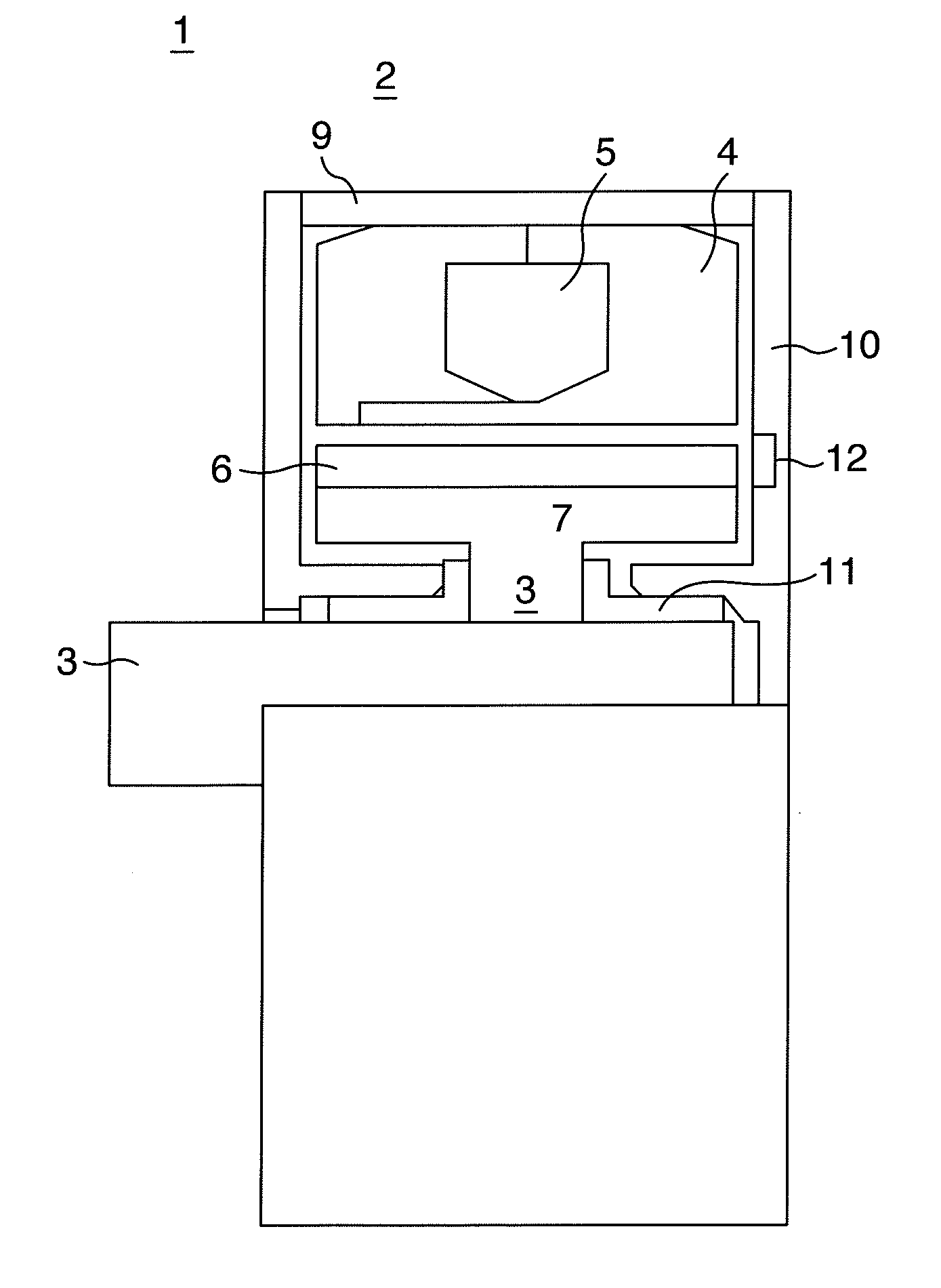
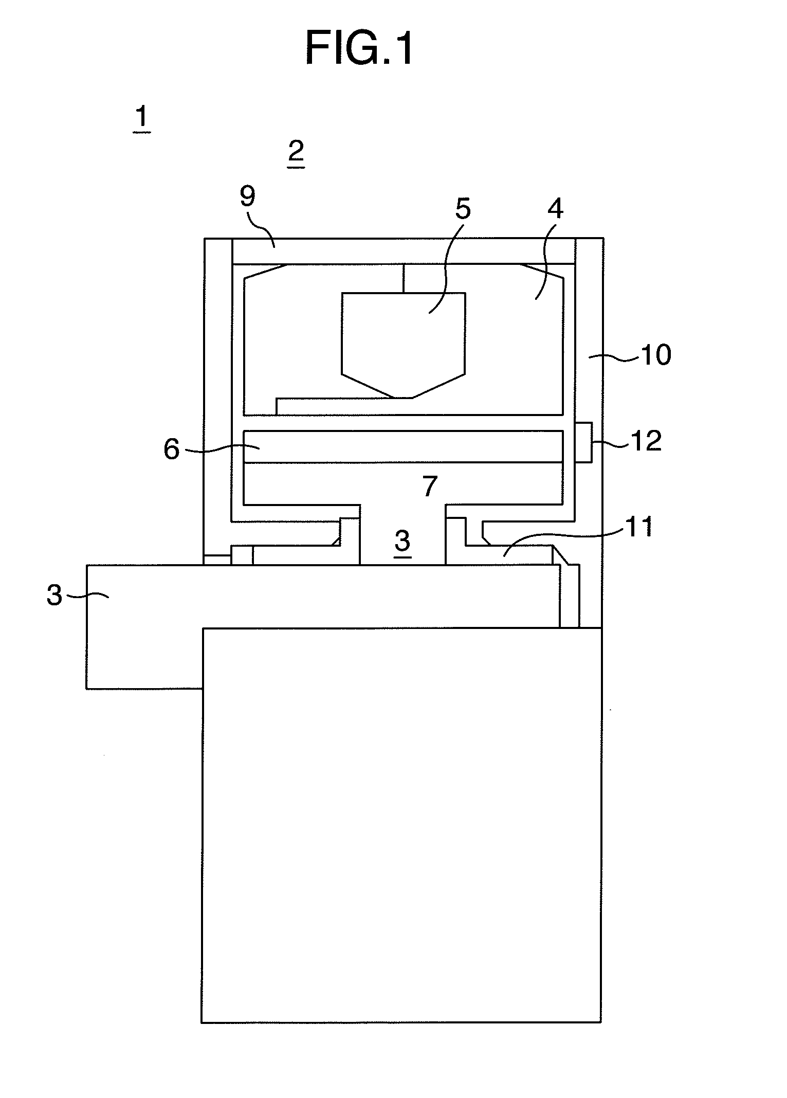
[0025] The configuration of a claw-pole type single-phase motor in one embodiment of the present invention comprising a stator, which is composed of a claw-pole type stator core and toroidally-wound stator windings, and a rotor that has permanent magnets will be described below with reference to FIG. 1 and FIGS. 2A and 2B.

[0026] Referring to the figures, a claw-pole type single-phase motor 1 comprises a stator 2 and a rotor 3. The rotor 3 comprises permanent magnets 6 and a rotor core 7 that constitutes the magnetic circuit and, via a shaft 8, transmits the power to an external device such as a pump.

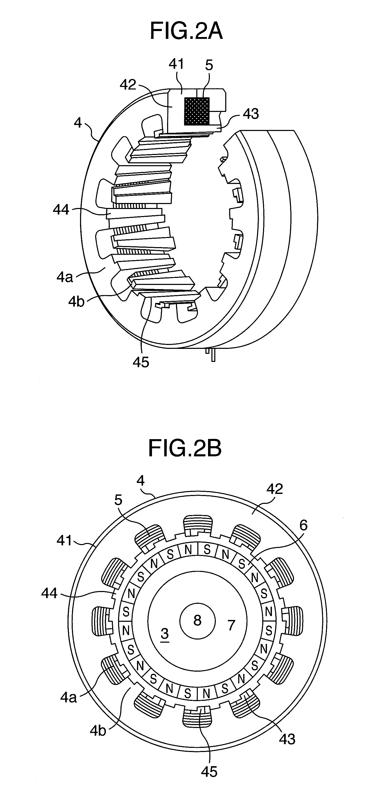
[0027] On the other hand, the stator 2 comprises a stator core 4 and stator windings 5. In this example, the stator core 4 comprises two stator cores 4a and 4b (claw-shaped magnetic pole), which have almost the same shape, and they have the toroidally-wound stator winding 5 in the center as shown in the figure. When the power voltage is low (usually, a low voltage of 12V in a vehicle),...


PUM


Abstract

A single-phase claw-pole type motor comprises a stator, which comprises a claw-pole type stator core and toroidally-wound single-phase stator windings, and a rotor that has alternate polarities, wherein a concave part or a convex part is provided on an air-gap surface of claws of the stator core. In addition, the stator core may be configured by compacting magnetic powder, and the single-phase claw-pole type motor may be driven by a converter that converts a direct current to an alternate current according to a position of the rotor.

Description

BACKGROUND OF THE INVENTION [0001] 1. Field of the Invention [0002] The present invention relates to a claw-pole type motor. [0003] 2. Description of Related Art [0004] The first measures practically used today for improving the fuel economy of a vehicle are to use an idle stop system, and the second measures are to employ a hybrid system in which a rotary electric machine is used for driving the vehicle. The problem with using those systems is that the idle stop system requires another pump driving source because the engine stops when the vehicle stops. On the other hand, a hybrid vehicle requires not only the idle stop system described above but also a driving motor or a starter generator, as well as a water pump for cooling its controller and, therefore, uses more motor-based electric pumps as their driving sources. [0005] An example of a water pump using a three-phase brushless motor is disclosed in JP-A-2003-328986 as a typical example. [0006] The structure of a general single-...

Claims


Application Information

Patent Timeline
Patent Type & Authority Applications(United States)
IPC IPC(8): H02K37/14H02K11/00H02K21/12H02P7/06H02K1/02H02K1/14H02K29/03H02K29/08
CPCH02K21/145H02P6/10H02K29/03
Inventor KAKUGAWA, SHIGERUTAJIMA, FUMIOKITAMURA, MASASHIENOMOTO, YUJIITO, MOTOYAMASAKI, RYOSOOHIWA, SHOJIISHIHARA, CHIO
Owner HITACHI IND EQUIP SYST CO LTD
Why Eureka
Try Eureka