Temperature expansion valve

A technology for expansion valves and passages, which is applied in the field of temperature expansion valves, and can solve problems such as unstable valve movements and incomplete control of oscillation phenomena

Inactive Publication Date: 2005-03-23
FUJIKOKI MFG CO LTD
View PDF0 Cites 0 Cited by
  • Summary
  • Abstract
  • Description
  • Claims
  • Application Information

AI Technical Summary

Problems solved by technology

[0015] However, the above-mentioned oscillation phenomenon is different according to the operating characteristics of each refrigeration cycle. Especially when the low-pressure refrigerant sent by the evaporator has a slight temperature change, the following situation often occurs, that is, the slight pulsation generated by the refrigerant will directly affect the temperature of the refrigerant. The opening and closing action transmitted to the valve body makes the valve action unstable, even if the thermal balance device or adsorbent is used, the oscillation phenomenon cannot be completely controlled

Method used


Image

  • Temperature expansion valve
  • Temperature expansion valve
  • Temperature expansion valve

Examples


Embodiment Construction

[0027] Hereinafter, embodiments of the temperature type expansion valve of the present invention will be described with reference to the drawings.

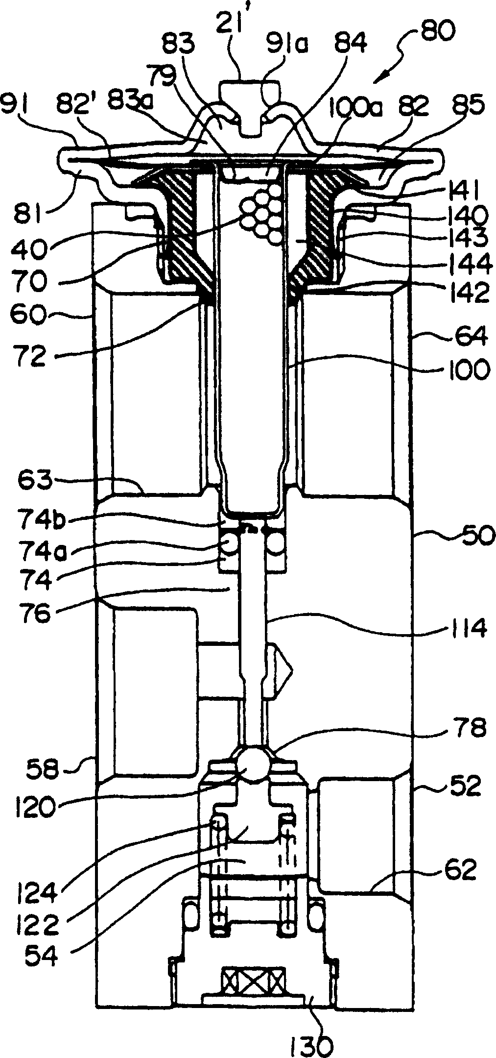
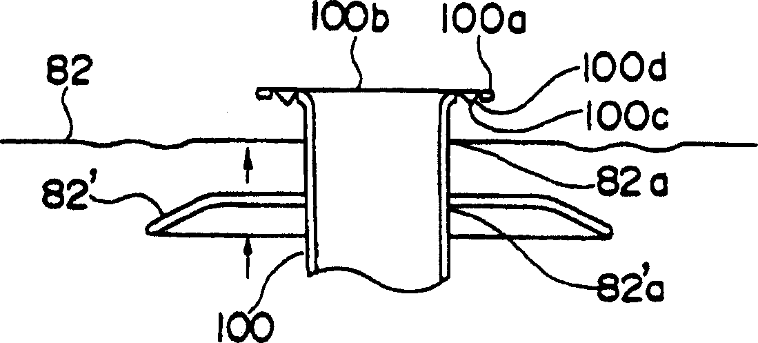
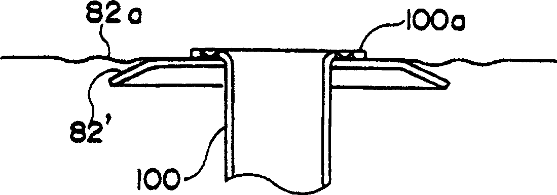
[0028] figure 1 2( a ) and FIG. 2( b ) are sectional views showing the structure of the main parts thereof. figure 1 The shown embodiment has the same basic structure as the existing temperature-type expansion valve, so only the parts with different structures will be described, and the parts that are the same as or equivalent to the existing temperature-type expansion valve use the same symbols, and their descriptions will be omitted. .

[0029] figure 1 Among them, symbol 140 is a heat conduction hysteresis member, for example, made of resin such as nylon or polyacetal, and made into a roughly cup shape, with a wide and thick wall with a flange portion 141 on the outside of the upper end and a tapered necking portion 142 at the lower end. The cylindrical part 143 is formed, and the upper end is in contact with the supporti...


PUM


Abstract

A thermostatic expansion valve suppressing a hunting phenomenon. A heat transmission retardant member is formed of a cup-like shaped, comprising a collar formed to the outside of the upper end thereof, and a thick-walled cylinder portion having at the lower end thereof a tapered portion. Said retardant member is positioned so that the upper end contacts a support member, said collar is supported by the inner surface of a housing, the outer surface of said cylinder portion contacts the inner surface of said housing, and the end of said tapered portion is inserted to a second hole and contacting the outer surface of a heat-sensing driven member and further positioned within a lower chamber defined by a diaphragm. Said retardant member is mounted to said driven member so as to cover the outer surface thereof and being mounted outside the second refrigerant passage, said tapered portion defining a space between the exterior of the driven member and the interior of said cylinder portion.

Description

technical field [0001] The invention relates to a temperature type expansion valve used in a refrigeration cycle. Background technique [0002] Now, in the refrigeration cycle, in order to control the flow rate of refrigerant supplied to the evaporator and decompress the refrigerant, use Figure 5 Thermostatic expansion valve shown. [0003] Figure 5 Among them, a first refrigerant passage 514 having an orifice 516 and a second refrigerant passage 519 are formed independently of each other on a prismatic valve body 510 made of aluminum. One end of the first refrigerant passage 514 communicates with the inlet of the evaporator 515, and the outlet of the evaporator 515 passes through the second refrigerant passage 519, the compressor 511, the condenser 512 and the receiving tank 513 and the other end of the first refrigerant passage 514. connect. In the valve chamber 524 communicating with the first refrigerant passage 514, there is provided an urgi...

Claims


Application Information

Patent Timeline
Patent Type & Authority Patents(China)
IPC IPC(8): F16K31/68F25B41/06
CPCF25B2341/0683F25B2341/0682F25B41/062F25B41/335
Inventor 箕轮昌贤渡辺和彦
Owner FUJIKOKI MFG CO LTD
Why Eureka
Try Eureka