Aeration valve and drain pipe system

A technology for ventilating valves and valve bodies, which is applied in the directions of valves, lifting valves, and control valves used for inflation. The effect of the oscillation phenomenon

Active Publication Date: 2019-10-29
KITZ CORP
View PDF10 Cites 0 Cited by
  • Summary
  • Abstract
  • Description
  • Claims
  • Application Information

AI Technical Summary

Problems solved by technology

Many magnets are required, so the number of parts increases, and the internal structure is complicated to install the magnets

Method used


Image

  • Aeration valve and drain pipe system
  • Aeration valve and drain pipe system
  • Aeration valve and drain pipe system

Examples


Embodiment Construction

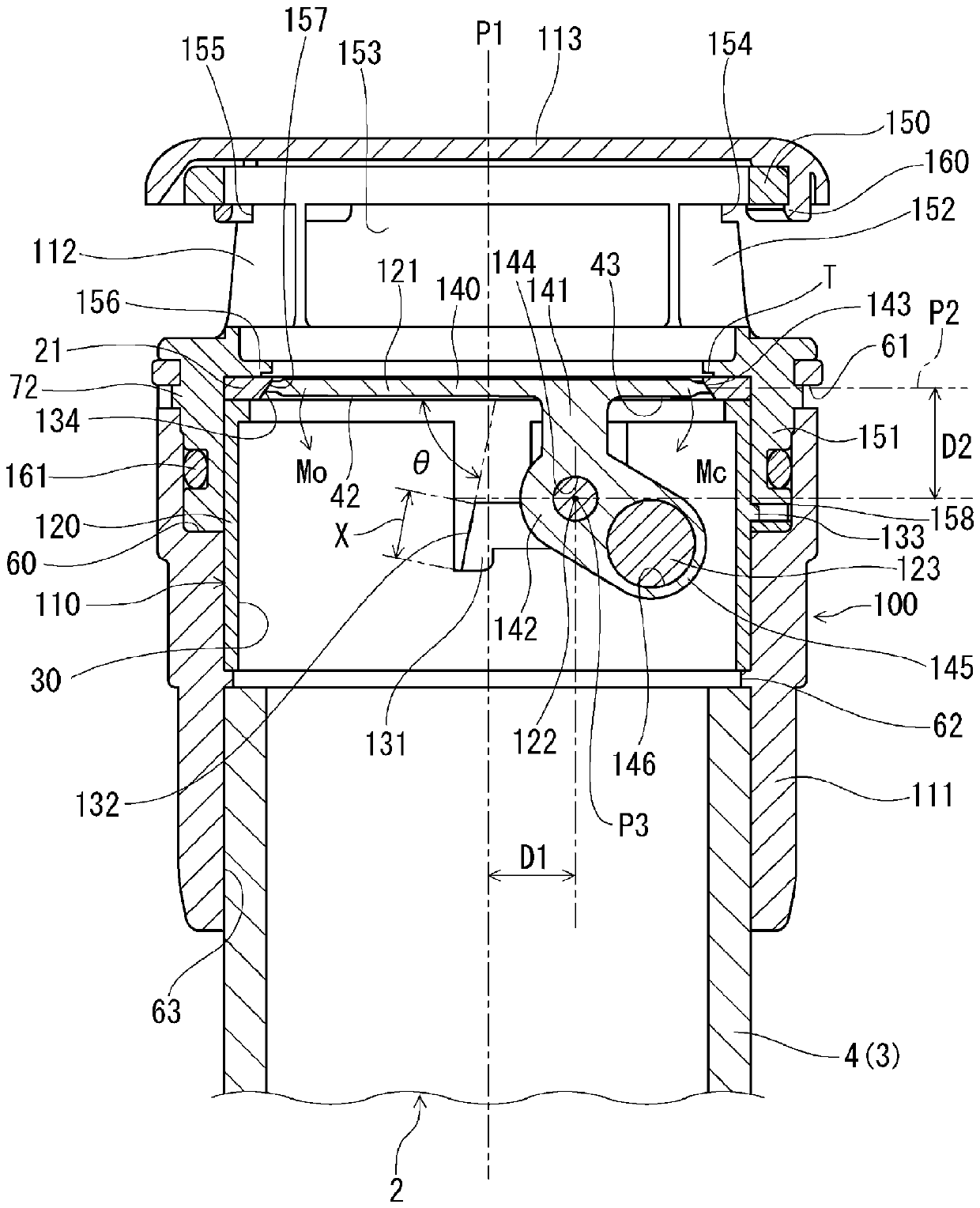
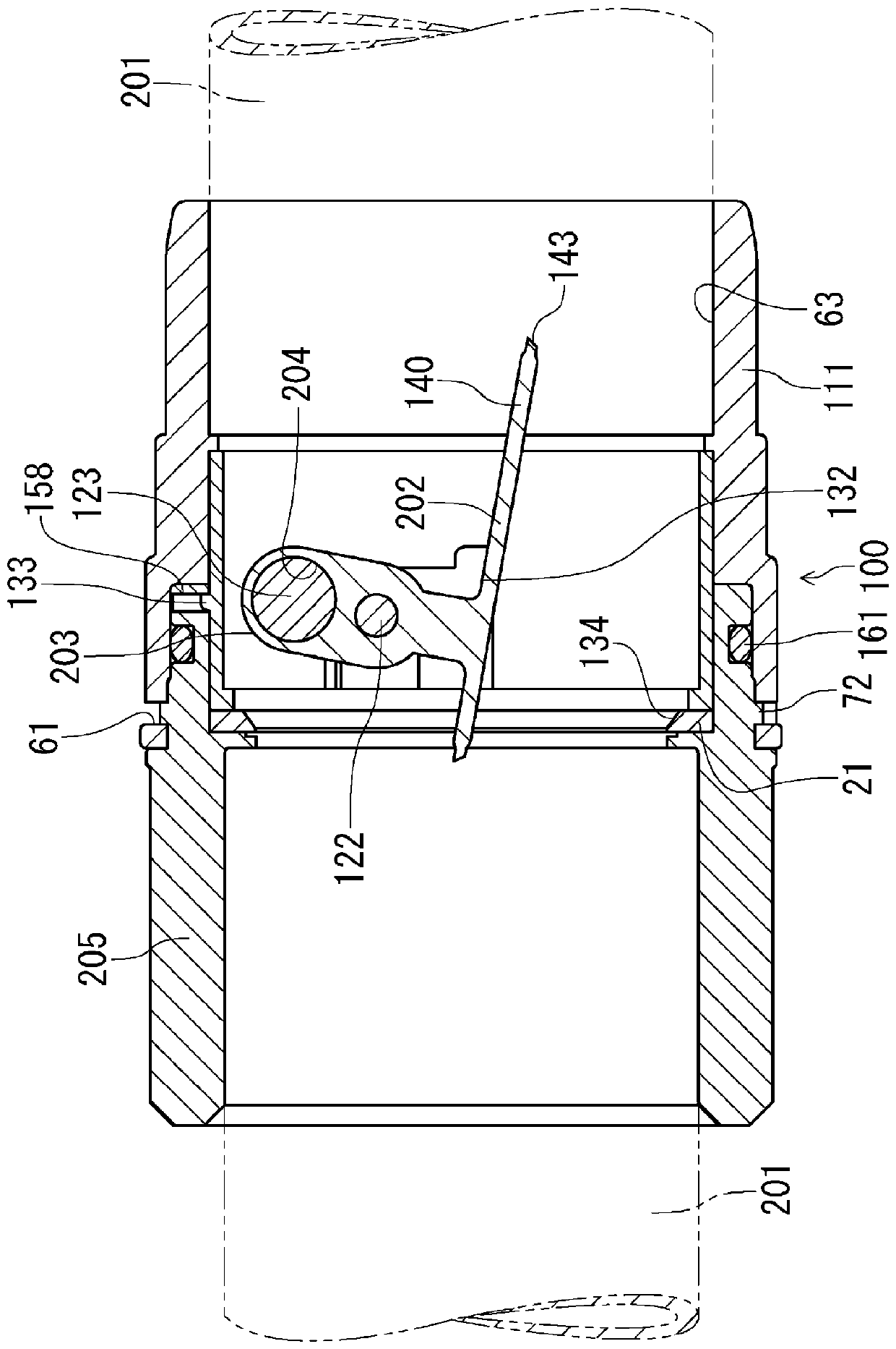
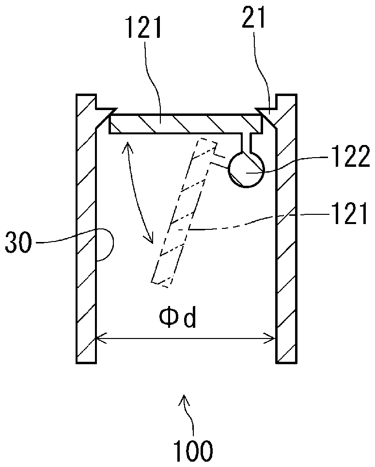
[0097] Hereinafter, the breather valve and drain pipe system of this invention are demonstrated in detail based on embodiment. exist Figure 1~Figure 3 , shows the first embodiment of the breather valve of the present invention. The breather valve (hereinafter referred to as the valve body 1) is set on Image 6 The drainpipe system shown (hereinafter referred to as system body 2).

[0098] exist Image 6 Among them, the system main body 2 is arranged between the outer wall 5 and the inner wall 6 of individual houses or collective houses, for example, and the valve main body 1 is arranged to pass through the ceiling ventilation pipe that extends from the drain pipe 3 to a position lower than the ceiling 7. 4 or the lower part of the overflow edge (あふれ縁) of the drainage equipment can eliminate the negative pressure generated in the drainage pipe 3 through the system main body 2. In this embodiment, an example in which the valve main body 1 is provided in the overhead vent pi...


PUM


Abstract

Provided are an aeration valve and a drain pipe system, which can prevent enlargement in the pipe diameter direction by means of a simple structure and are arranged in a piping space which is approximately the same as that of a vent pipe, maintain a closed valve state while exhibiting high sealing properties at atmospheric pressure or positive pressure, and reliably eliminate negative pressure while suppressing oscillation by operating a valve body with high responsiveness in a state in which ventilation resistance is suppressed to be small and ventilation amount is ensured to be large when negative pressure occurs. The aeration valve is installed so as to be able to open and close by means of a circular plate valve body (23) incorporated in a pipe main body (20) so as to rotate around anaxis of rotation (24). The circular plate valve body (23), in case of negative pressure in the pipe main body (20), generates an unbalanced torque that rotates in the opening direction via the axis ofrotation (24), and allows admission of air from the outside. In the pipe main body (20), at atmospheric pressure or positive pressure, an unbalanced torque is generated and rotates in the closing direction via the axis of rotation (24) and closes the valve.

Description

technical field [0001] The present invention relates to a breather valve and a drainpipe system connected to a drainpipe to eliminate negative pressure generated in the drainpipe. Background technique [0002] In the past, in the drainage equipment of buildings such as individual houses and collective housing, in order to eliminate the negative pressure in the drainage pipe, protect the backwater trap of the drainage device and seal the water, and drain the water smoothly, a drainage pipe system using a vent valve is generally known. [0003] As a vent valve used in such a drain pipe system, for example, a safety valve disclosed in Patent Document 1 is disclosed. In this valve, the structure is set as follows: two concentric valve seats are provided in the inner chamber of the shell connected to the ventilation pipe, and the valve body with the ring-shaped sealing member installed on the sleeve (ブブ) is opposed to the valve seat. Lifting and lowering, the flow path for sucti...

Claims


Application Information

Patent Timeline
Patent Type & Authority Applications(China)
IPC IPC(8): F16K24/06E03C1/122E03C1/295F16K1/22F16K15/03
CPCE03C1/122E03C1/295F16K1/22F16K15/03F16K24/06
Inventor 青木和弘小幡浩小林达朗
Owner KITZ CORP
Why Eureka
Try Eureka