A hydraulic circuit of a transmission

A transmission and oil circuit technology, applied to components with teeth, transmission parts, belts/chains/gears, etc., can solve problems such as internal pressure drop, oscillation, etc., and achieve the effect of preventing insufficient oil pressure

Active Publication Date: 2020-02-11
HONDA MOTOR CO LTD
View PDF10 Cites 0 Cited by
  • Summary
  • Abstract
  • Description
  • Claims
  • Application Information

AI Technical Summary

Problems solved by technology

[0004] However, if the above-mentioned switching conditions between the high-voltage mode and the low-voltage mode are fixed, a so-called hunting phenomenon in which the low-voltage mode and the high-voltage mode are frequently switched may occur.
That is, there may be a phenomenon in which the following processes are repeated: transient internal pressure drop of the torque converter → automatic switching to the high-pressure mode → restoration of the internal pressure of the torque converter with sufficient line pressure → automatic switching to the low-voltage mode Switching → Transient internal pressure drop of the torque converter

Method used


Image

  • A hydraulic circuit of a transmission
  • A hydraulic circuit of a transmission
  • A hydraulic circuit of a transmission

Examples


Embodiment Construction

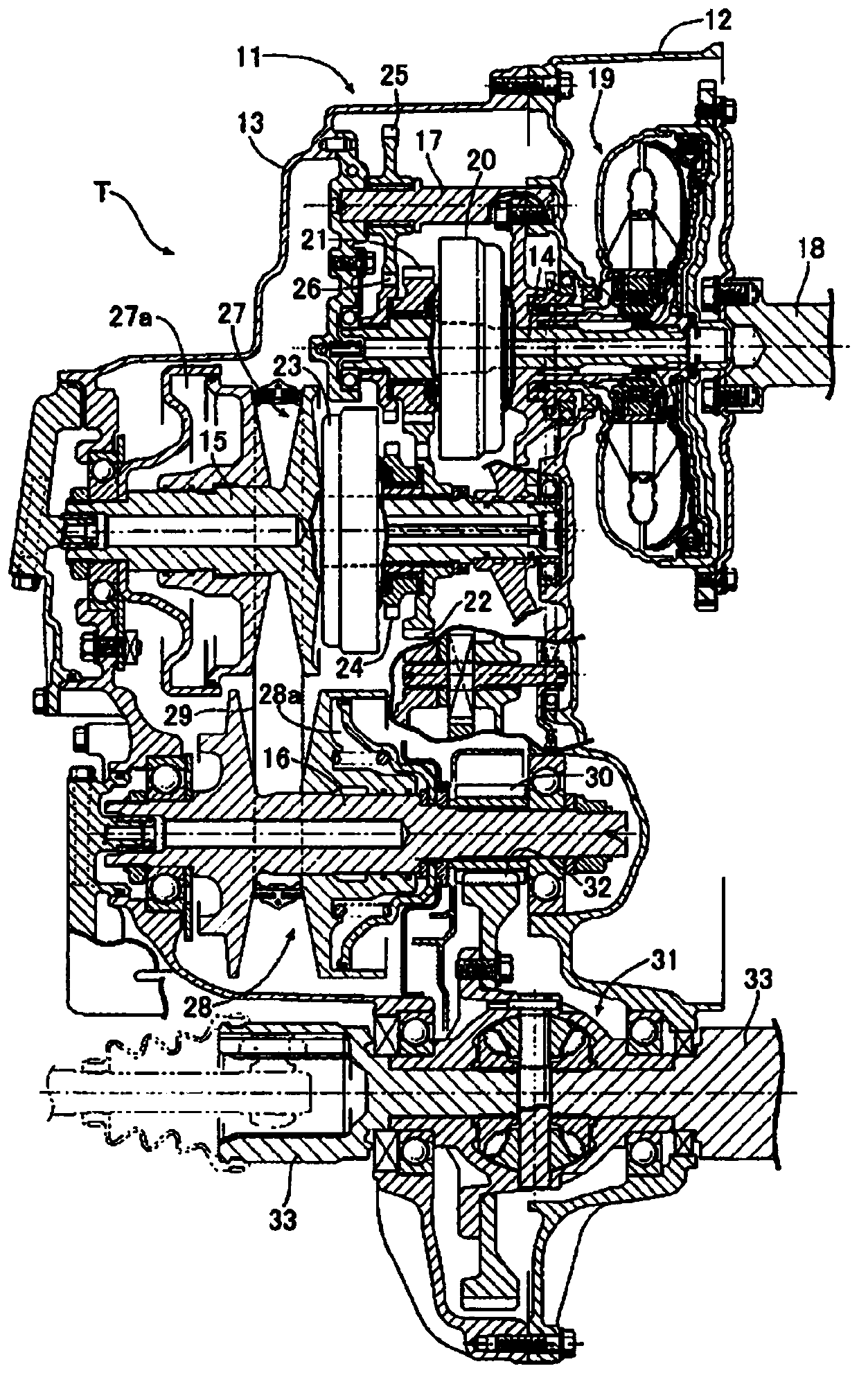
[0102] Hereinafter, embodiments of the present invention will be described with reference to the drawings. figure 1 It is a longitudinal sectional view of a belt type continuously variable transmission mechanism which is one form of the transmission of the present invention. First, use figure 1 , illustrating the overall structure of the belt type continuously variable transmission T. The transmission case 11 of the belt-type continuously variable transmission T includes a torque converter case 12 combined with an engine not shown, and a transmission case body 13 combined with the torque converter case 12 , inside the transmission case 11 , supporting an input shaft 14 , a drive pulley shaft (drive pulley shaft) 15 , a driven pulley shaft (driven pulley shaft) 16 and an idle shaft (idle shaft) 17 in parallel.

[0103] On the input shaft 14 connected to the crankshaft 18 of the engine via a torque converter 19, a forward drive gear 21 capable of being coupled to the input sha...


PUM


Abstract

The invention provides a hydraulic circuit of a transmission, which can prevent insufficient oil pressure supplied to a control target on the one hand, and effectively suppress an oscillation phenomenon caused by frequent switching between a high-pressure mode and a low-pressure mode. The hydraulic circuit includes a check valve (V8), which is inserted between a main pump (PM) and an auxiliary pump (PS) and which is opened when the discharge pressure of the auxiliary pump (PS) is higher than that the discharge pressure of the main pump (PM); and a fourth oil passage (L4) supplied with the discharge pressure of the main pump (PM) and the auxiliary pump (PS) and is conducted through a solenoid valve (V5), or the oil pressure of the fourth oil passage (L4) is lower than a predetermined valueso as to disconnect the first oil passage (L1) and the second oil passage (L2) switched by a switching valve (V2). On the other hand, by turning off the solenoid valve (V5), the first oil passage (L1)and the second oil passage (L2) which are switched by the switching valve (V2) are disconnected.

Description

technical field [0001] The present invention relates to an oil pressure circuit of a transmission. Specifically, it relates to an oil pressure circuit comprising a main pump and a subpump, which is configured to supply the oil sprayed by the main pump to the transmission control system, and supply the oil sprayed by the subpump to the transmission control system. The output oil is supplied to the oil pressure circuit of the transmission of the lubrication system. Background technique [0002] Conventionally, as a hydraulic circuit of a transmission mounted on a vehicle, for example, as shown in Patent Document 1, oil is supplied to a sheave oil chamber of the transmission through a main pump and a sub pump simultaneously driven by an engine, a torque converter ( torqueconverter) and the hydraulic circuit of the lubrication system. In the hydraulic circuit disclosed in Patent Document 1, the low-pressure mode (lubrication mode) in which the discharge pressure of the auxiliar...

Claims


Application Information

Patent Timeline
Patent Type & Authority Applications(China)
IPC IPC(8): F16H61/00F16H57/04
CPCF16H57/0435F16H57/0436F16H57/0446F16H61/0031F16H2061/0037
Inventor 韮泽英夫
Owner HONDA MOTOR CO LTD
Why Eureka
Try Eureka