Device for fixating and adjusting the positions of vertebrae in vertebral surgical operations
What is Al technical title?
Al technical title is built by PatSnap Al team. It summarizes the technical point description of the patent document.
A technique for surgical operation and locking device, applied in the direction of fixator, internal fixator, internal bone synthesis, etc., can solve the problems of difficult device, uncomfortable patient, difficult device operation, etc.
Inactive Publication Date: 2005-05-11
斯文·奥勒鲁德
View PDF0 Cites 0 Cited by
Summary
Abstract
Description
Claims
Application Information
AI Technical Summary
This helps you quickly interpret patents by identifying the three key elements:
Problems solved by technology
Method used
Benefits of technology
Problems solved by technology
Devices used for this purpose are often bulky and make the patient very uncomfortable
These known devices are often difficult to apply, the design is complex and often illogical, making operation of the device difficult
Method used
Image
Click on the blue label to locate the original text in one second.
Reading with bidirectional positioning of images and text.
Examples
Embodiment Construction
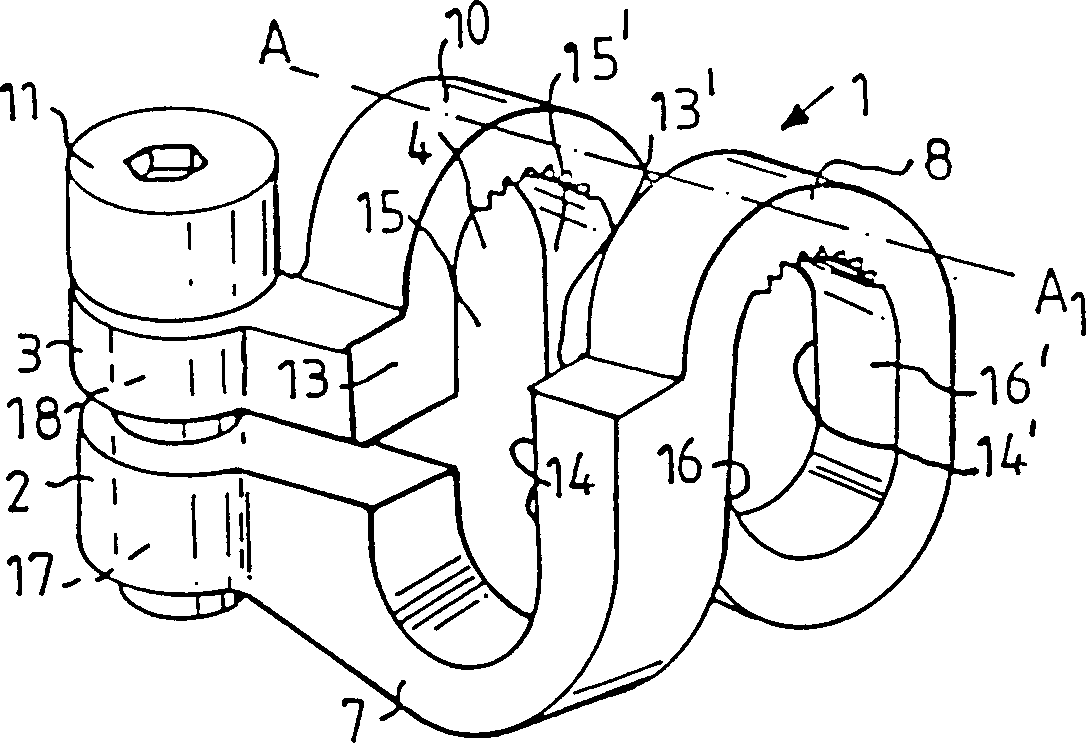
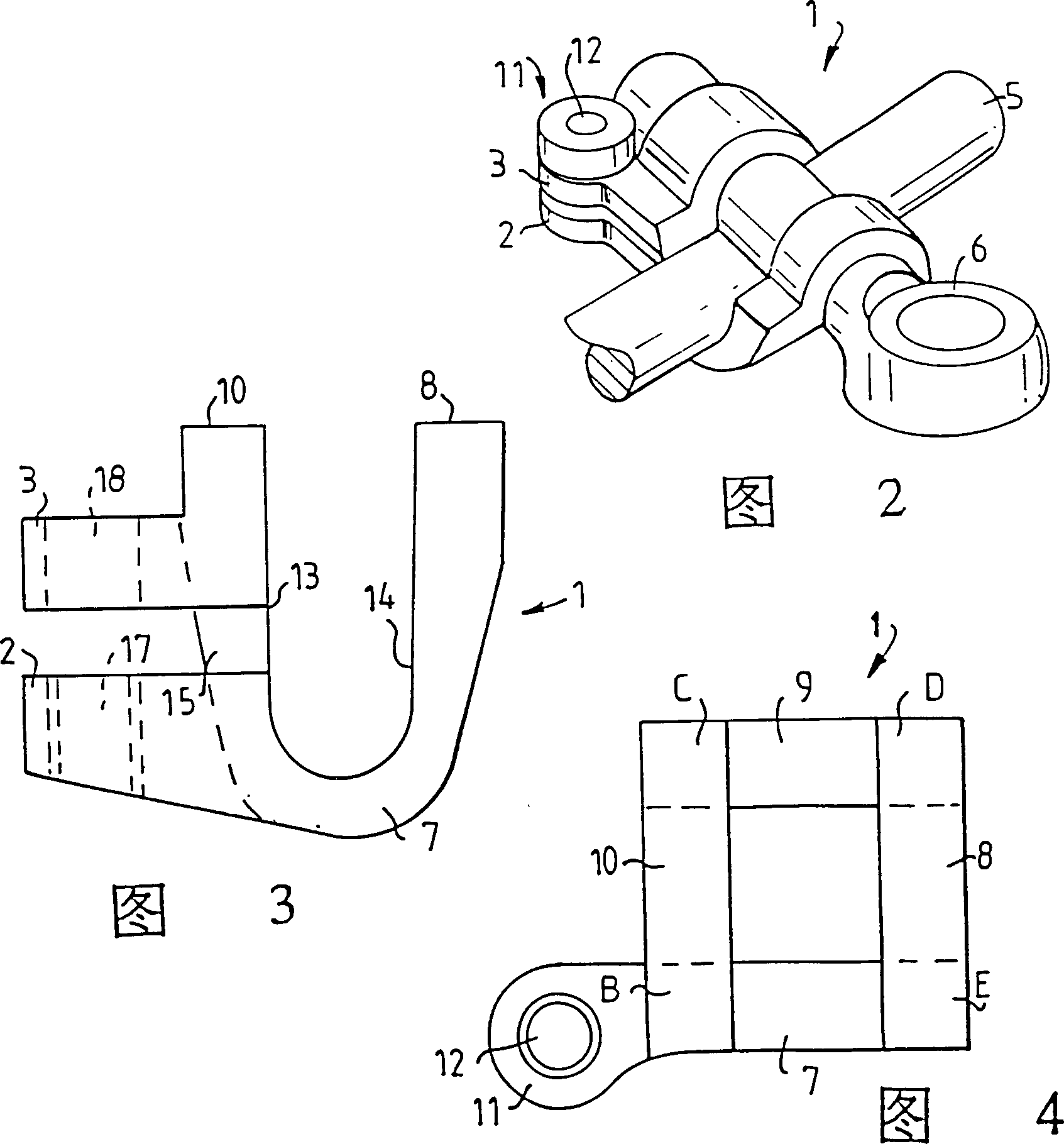
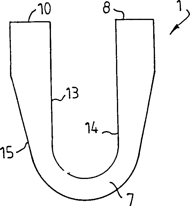
[0022] figure 1 4 to 4 represent the main components of an embodiment of the device of the present invention. As can be seen from these figures, this device consists of an elongated locking member 1 having two free ends 2, 3 and comprising a so-called hoop-shaped clamping and clamping part 4, which clamps The holding and clamping part 4 surrounds the rod-shaped implant elements 5, 6, and it is bent at an angle of 180° around the center line A-A from a substantially horizontal state to form two bottom hoops 7, 9 and two top hoops Rings 8, 10 which enclose rod-shaped implant elements 5, 6 in pairs, wherein the free ends 2, 3 of the locking parts comprise hoop-shaped clamping and clamping portions 4 and are equipped with locking and displacement means 11. The locking and shifting device 11 displaces the respective free ends relative to each other and can be locked in a set position. Each free end 2, 3 includes a flange protruding outwards substantially at right angles from the ...
PUM
Abstract
The present invention relates to a device for fixing and adjusting the position of the spine in spinal surgery, which comprises two interdigitated substantially rod-shaped implant elements. In order to lock the implant elements together, the device (1) also includes four generally parallel elongated elements (B, C, D, E) extending into a plane passing through two of them, their The ends are generally located at the corners of a parallelogram, preferably a square. The ends of the elongated elements are joined to each other in pairs by means of mutually parallel partial hoops (7, 9; 8, 10) bent outwards from the ends of the elongated elements, wherein at the ends of the elongated elements A pair of partial hoops (7, 9) at one end are perpendicular to the pair of partial hoops (8, 10) at the other end of the elongated element, wherein each pair of partial hoops attaches the rod-shaped implant element (5, 6, 11a, 17) and each adjacent intersecting rod-shaped member, wherein those sides (13, 14, 13', 14'; 15, 16, 15', 16 ′) are substantially flat and substantially parallel to respective opposing sides of adjacent elongate members when fixing and adjusting the position of the spine.
Description
technical field [0001] The present invention relates to a device for fixing and adjusting the position of the spine during spinal surgery, comprising two interdigitated, generally rod-shaped implant elements. Background technique [0002] It is known in the art to propose many different solutions for locking and securing two generally rod-shaped implant elements placed one above the other in order to correct and stabilize adjacent vertebrae. Devices used for this purpose are often bulky and very uncomfortable for the patient. These known devices are often difficult to apply, having a complex and often illogical design, making operation of the device difficult. Contents of the invention [0003] The object of the present invention is to eliminate the aforementioned disadvantages of the known devices for locking and securing substantially rod-shaped implant elements and to provide a device that can be quickly and flexibly operated...
Claims
Application Information
Patent Timeline
Application Date:The date an application was filed.
Publication Date:The date a patent or application was officially published.
First Publication Date:The earliest publication date of a patent with the same application number.
Issue Date:Publication date of the patent grant document.
PCT Entry Date:The Entry date of PCT National Phase.
Estimated Expiry Date:The statutory expiry date of a patent right according to the Patent Law, and it is the longest term of protection that the patent right can achieve without the termination of the patent right due to other reasons(Term extension factor has been taken into account ).
Invalid Date:Actual expiry date is based on effective date or publication date of legal transaction data of invalid patent.