Sealing collar

A technology for sealing leather cups and clamping parts, which is applied to the sealing of engines, other washing machines, washing devices, etc., and can solve the problems of inability to freely design the geometry of the connecting part and high installation costs.

Inactive Publication Date: 2005-07-20
BOSCH SIEMENS HAUSGERATE GMBH
View PDF0 Cites 0 Cited by
  • Summary
  • Abstract
  • Description
  • Claims
  • Application Information

AI Technical Summary

Problems solved by technology

[0004] Disadvantages of this known sealing cup are that high installation costs are required for fastening the sealing cup and that the geometry of the connection cannot be freely designed since the clamping part can be attached from the outside and is visible

Method used


Image

  • Sealing collar
  • Sealing collar
  • Sealing collar

Examples


Embodiment Construction

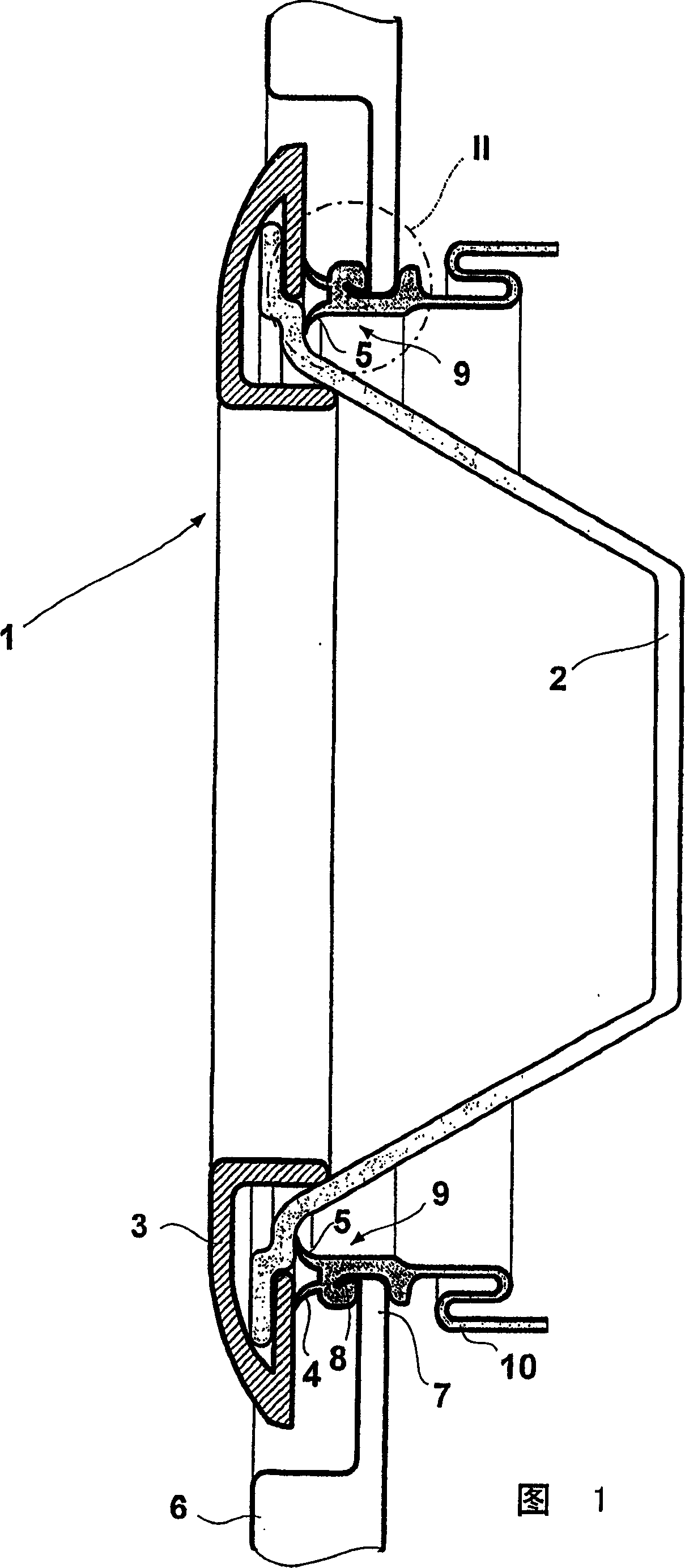
[0017] The cross-sectional view of the door area of ​​the front loading washing machine in FIG. 1 shows a sealed round window door 1 . The window door consists of a basin-shaped glass window 2 fixed on a door frame 3. On the inner side of the edge area of ​​the window door 1, sealing lips 4, 5 are attached to the closing part of the door. overflow from the washing machine cavity on the side.

[0018] The window door 1 is fastened via a hinge (not shown) to the window of a housing 6 of the washing machine, which has a beading 8 rolled forward in the edge region 7 of the window. The projection 9 of the outside of a sealing cup 10 is buckled on this flange. A clamping element embedded in the projection, such as an annular helical spring, clamps the projection 9 in the groove of the crimping projection 8 .

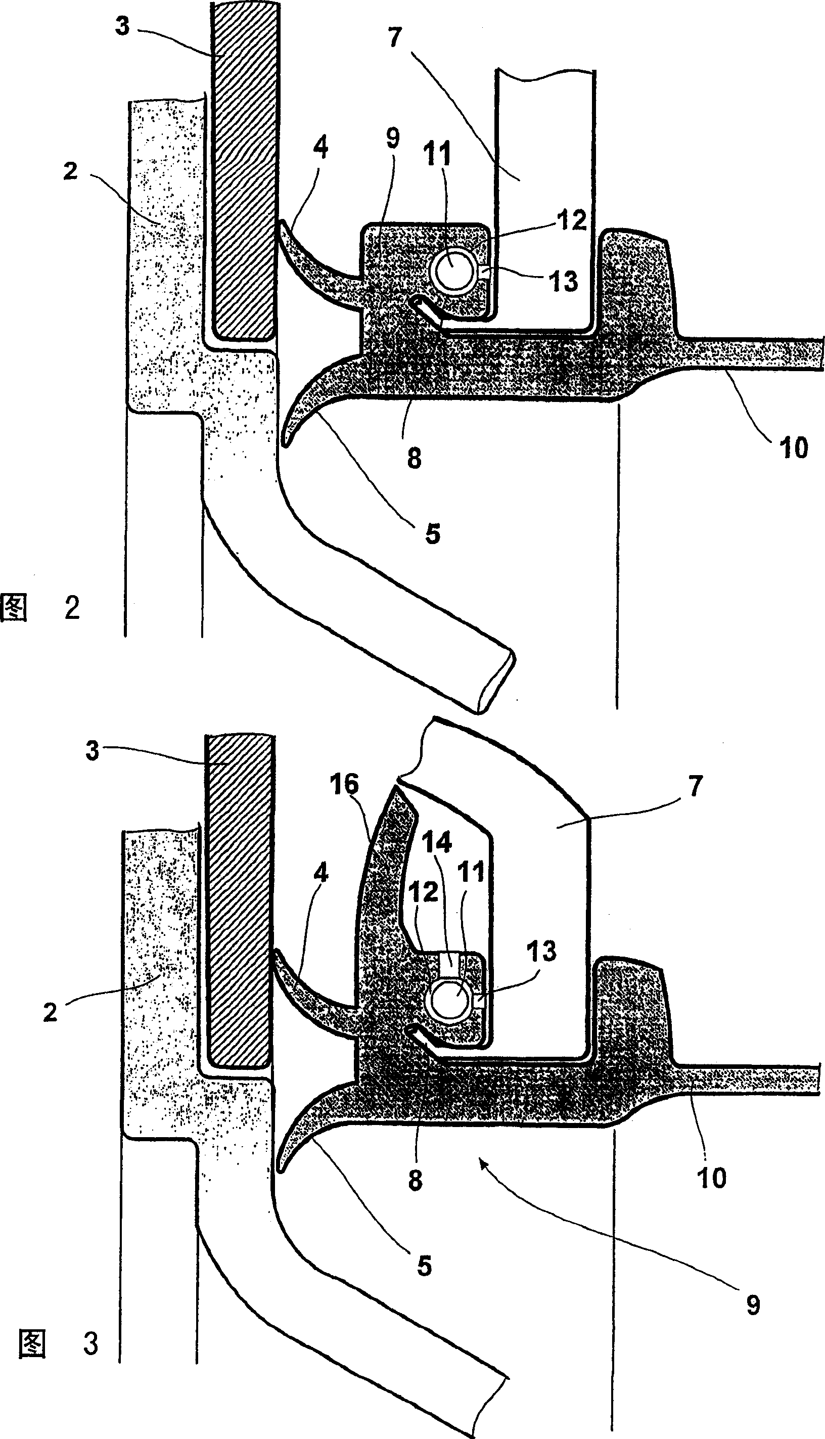
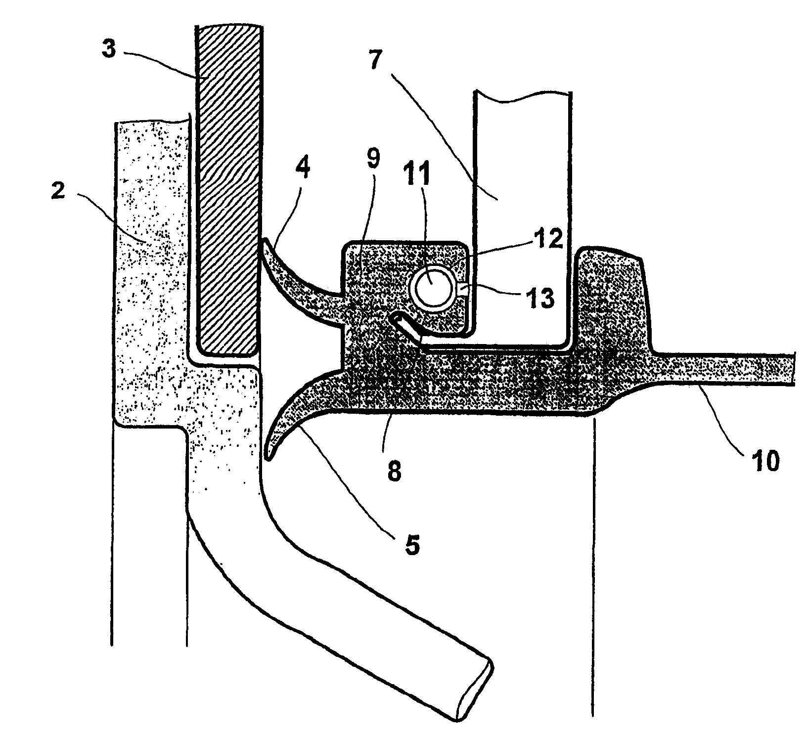
[0019] FIGS. 2 and 3 show in enlarged sectional views the projection 9 of the sealing cup 10 which has an annular channel 12 inside it. In FIG. 2 the channel 12 is connecte...


PUM


Abstract

A sealing sleeve seals joints in household appliances, especially the joints between the suds container and the front wall of the housing or the upper part of the suds container and the top frame in washing machines, and can be secured to the appliance by a substantially annular clamping element. The clamping element can be molded into the interior of the section (which can be a beading) of the sealing sleeve to be secured.

Description

technical field [0001] The present invention relates to a sealing cup for sealing the joint of a household appliance, in particular the joint between the outer drum and the front wall of the housing of a washing machine or the joint between the upper part of the lye container and the cover frame, which can be used It is held in place by an essentially annular clamping element. Background technique [0002] In a washing machine or washer-dryer, it is very important to ensure a proper seal between the outer drum and the housing front wall of a front-loading washer and between the upper portion of the lye pot and the cover frame of a top-loading washer. For this purpose, sealing cups are usually used which are fastened by means of known clamping elements or clamping / screw elements arranged around the sealing cup. [0003] From DE-OS2403705 discloses a kind of sealing cup, it forms sealing connection between the lye container of the washing machine wherein the washing drum is p...

Claims


Application Information

Patent Timeline
Patent Type & Authority Patents(China)
IPC IPC(8): D06F37/10D06F37/18D06F37/26D06F39/14F16J15/10
CPCD06F37/266D06F39/14D06F37/26
Inventor K·尼特施曼W·普罗佩
Owner BOSCH SIEMENS HAUSGERATE GMBH
Why Eureka
Try Eureka