Buckle assembly for adjusting straps for headgear and swimming glasses with said assembly
A technology for swimming goggles and buckles, which is applied in the field of swimming goggles and can solve problems such as inconvenient adjustment operations
- Summary
- Abstract
- Description
- Claims
- Application Information
AI Technical Summary
Problems solved by technology
Method used
Image
Examples
no. 1 example
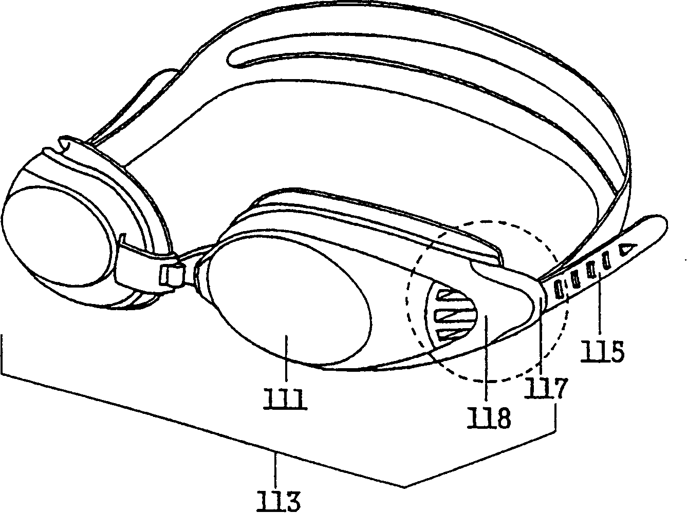
[0082] image 3 and 4 Perspective and exploded views of a swimming goggle having a buckle assembly 100 of a first embodiment of the present invention are shown.
[0083] The swimming goggle includes a mirror assembly 113 and an elastic strap 115 that secures the swimming goggle to the wearer's head. The mirror assembly 113 includes a pair of lenses 111 and a pair of frames 118, each frame 118 incorporating a lens 111 therein.
[0084] According to the present embodiment, the buckle assembly 100 is detachably connected to each outer portion of the mirror assembly 113 to connect the mirror assembly 113 and the elastic strap 115 . In order to secure the buckle assembly 100 on such as Figure 4 On the outer portions of the mirror assembly 113 shown, on each outer portion of the lens 111 is provided a retainer such as a spacer protrusion 118a. Spacer ribs 118b ( Figure 13 ) is press-fitted between these projections 118a, which will be further described below. In this manner, ...
no. 2 example
[0098] refer to Figure 14 and 15 , respectively show a perspective view and an exploded view of a swimming goggle having a buckle assembly 200 according to a second embodiment of the present invention.
[0099] Attached to each end of a respective lens 211 are two straps 215 and 215', each having a plurality of transverse ridges 215a and 215a', as shown. Each elastic strap 215 and 215' is wrapped around a corresponding first and second strap support portion 219a and 219a', both of which are formed within a single buckle assembly 200. The buckle assembly 200 of this embodiment is formed separately from the mirror assembly 213 .
[0100] The buckle assembly 200 of the present embodiment includes a buckle body 219 having first and second belt support portions 219a and 219a' around which first and second belts 215 and 215' are respectively wound. The first and second sliders 217 and 217' are slidable between a first position and a second position relative to the first and seco...
no. 3 example
[0108] refer to Figure 16 and 17 , respectively show a perspective view and an exploded perspective view of a swimming goggle having a buckle assembly 300 according to a third embodiment of the present invention.
[0109] In this example, if Figure 17 As shown, a belt support portion 319a is formed on each end of the mirror body 311 together with two spaced protrusions 318a on which the frame is fastened.
[0110] To guide the sliding movement of the slider 317 between its first and second positions, a pair of parallel guide rails 317c are formed on the outer side portion of the mirror frame 318 . The slider 317 includes a pair of bracket portions 317e, each of which is inserted into a guide rail to be slidable along the guide rail 317c. A belt pressing piece 317b is formed separately from the slider 317, and is connected to the bracket part 317e of the slider 317 inserted in the guide rail 317c. Belt pressing piece 317b is adapted to press belt 315 against belt support ...
PUM
 Abstract
Description
Claims
Application Information
 - R&D
- Intellectual Property
- Life Sciences
- Materials
- Tech Scout
- Unparalleled Data Quality
- Higher Quality Content
- 60% Fewer Hallucinations
Browse by: Latest US Patents, China's latest patents, Technical Efficacy Thesaurus, Application Domain, Technology Topic, Popular Technical Reports.
© 2025 PatSnap. All rights reserved.Legal|Privacy policy|Modern Slavery Act Transparency Statement|Sitemap|About US| Contact US: help@patsnap.com


