
Cooling method and device for high-temperature discharge gas and combustion treating device

A technology for exhausting gas and cooling device, which is applied in the field of combustion treatment device, can solve the problems of not being large, the cooling device cannot, and cannot allow the gas to circulate and drain the structure, etc., and achieve the effect of improving the gas-liquid contact efficiency and the cooling efficiency.

Inactive Publication Date: 2005-11-16
NIPPON SANSO CORP +2
View PDF1 Cites 0 Cited by
  • Summary
  • Abstract
  • Description
  • Claims
  • Application Information

AI Technical Summary

Problems solved by technology

[0005] However, in the above-mentioned known cooling device, in order to cool the high-temperature exhaust gas, a large amount of water must be used, and even a large cooling chamber must be used in order to completely contact the exhaust gas with water.
What's more, the demisting device installed outside the cooling chamber to remove solid matter or water droplets from the exhaust gas must adopt a drainage structure that cannot allow the gas to circulate
Therefore, the overall size of the cooling device cannot be reduced.

Method used


Image

  • Cooling method and device for high-temperature discharge gas and combustion treating device
  • Cooling method and device for high-temperature discharge gas and combustion treating device
  • Cooling method and device for high-temperature discharge gas and combustion treating device

Examples


example

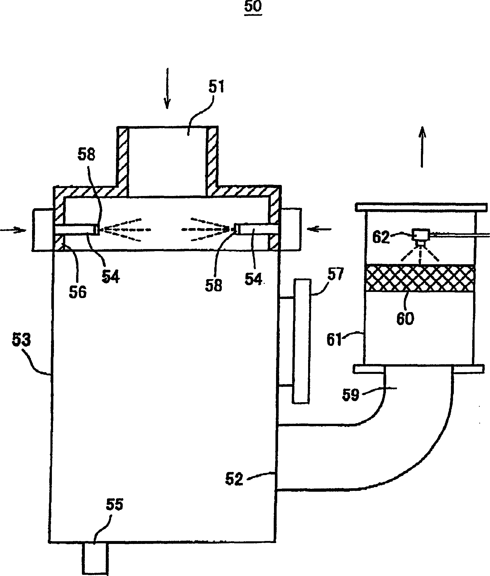
[0076] use Figure 5 The combustion chamber of the structure shown will be composed of 3% silane (silane, SiH 4 ) Combustion treatment target gas composed of nitrogen gas is introduced into the combustion chamber from the gas introduction pipe at a rate of 200 liters (litter) per minute, and a flat flame formed by using LPG as fuel and air as a combustion-supporting gas in the burner, Burn silane for detoxification treatment. At this time, a high-temperature exhaust gas of about 1000 degrees Celsius occurs from the combustion chamber at a rate of 800 liters per minute.

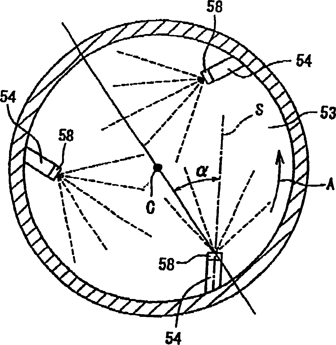
[0077] Here, using the cooling device of the aforementioned first preferred embodiment in which the spray axis of the spray nozzle 54 is arranged toward the center of the cooling chamber, the aforementioned high-temperature exhaust gas is cooled with 5 liters of water per minute, and discharged from the cooling chamber. The temperature of the gas discharged from the gas discharge unit is about 73 degrees Celsi...


PUM


Abstract

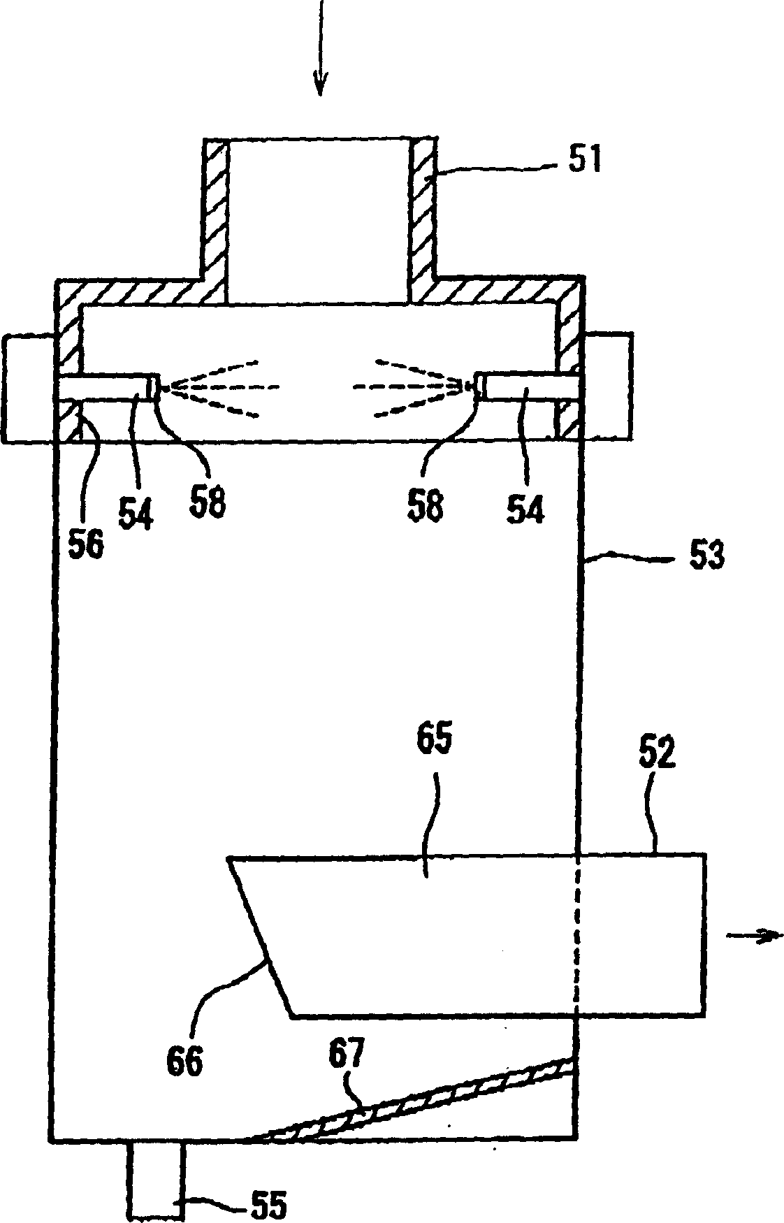
Provided are a method and an apparatus for cooling a high-temperature exhaust gas, capable of cooling effectively the high-temperature exhaust gas with a small amount of water, as well as, a combustion treatment equipment provided with the cooling apparatus. According to this method, a water curtain is formed orthogonal to the flow of the exhaust gas within a passage through which the high-temperature exhaust gas flows, and the high-temperature exhaust gas is allowed to pass through the water curtain to be cooled thereby. The cooling apparatus is provided with cylindrical cooling chamber (53) having at an upper position a high-temperature exhaust gas inlet (51) and at a lower position a cooled exhaust gas outlet (52); and a plurality of water spray pipes (54) arranged near the high-temperature exhaust gas inlet. Spray nozzles (58) of the water spray pipes (54) are arranged such that spouting axes of the nozzles (58) direct toward the center of the cooling chamber (53) substantially on the same horizontal plane and that water droplets spouted through the respective spray nozzles impinge against one another.

Description

technical field [0001] The present invention relates to a cooling method and device for high-temperature exhaust gas and a combustion treatment device, and particularly relates to a method for cooling high-temperature exhaust gas discharged along with various combustion treatments and its device structure, and a device with the cooling device Combustion treatment device. Background technique [0002] High-temperature exhaust gas is generated during iron manufacturing, incineration of trash, and combustion treatment of toxic components. This high-temperature exhaust gas is not allowed to be released into the atmosphere as it is for the sake of preventing public nuisance. Therefore, it is usually necessary to cool the exhaust gas before discharging it. [0003] Figure 7 Shown is a longitudinal sectional view of an example of a known exhaust gas cooling device. The high-temperature exhaust gas is introduced into the cooling chamber 12 constituting the cooling device 11 from...

Claims


Application Information

Patent Timeline
Patent Type & Authority Patents(China)
IPC IPC(8): B01D47/06F23G7/06F23J15/04F23J15/06F28C3/06
CPCF23J2219/80F23J15/04F23G7/065F23G7/063Y02E20/363F23J15/06
Inventor 杉森由章小岛孝小关修一万行大贵富田修康小野宏之白濑溥
Owner NIPPON SANSO CORP
Learn More