Multi -Channeled Flat Tube And Heat Exchanger

a flat tube and multi-channel technology, applied in the field of construction, can solve the problems of reducing the contact surface area between the outer surface of the tube and the fin, reducing the heat transfer performance, and unable to achieve desired performance, and achieve the effect of increasing heat transfer efficiency

Inactive Publication Date: 2008-04-17
GLOSTER
View PDF1 Cites 12 Cited by
  • Summary
  • Abstract
  • Description
  • Claims
  • Application Information

AI Technical Summary

Benefits of technology

[0014] A pressure that is equal to or greater than the pressure used during tube expansion is not a normal operating pressure of a multi-channeled flat tube. If such pressure were applied during normal operation, there would be the possibility of further deformation in the multi-channeled flat tube since this is not how multi-channeled flat tubes are designed. Accordingly, the pressure used during tube expansion is an upper limit of the withstand pressure conditions for normal operation or even higher. Also, the pressure used during tube expansion is set up to at a pressure whereby the partitions become straightened out and is not set at a pressure whereby stretch deformation of partitions, which makes the partitions thinner, commences. This means it is economical to set the thickness of the outer tubes so that the outer walls deform at a pressure where stretch deformation, which makes the partitions thinner, commences. The heat transfer efficiency also increasing when thin outer tubes are used.

Problems solved by technology

This would reduce the contact surface area between the tube outer surface and the fins and reduce the heat transfer performance.
However, if tube expansion is stopped before the partitions have extended to reach the desired size, the desired performance cannot be obtained.

Method used


Image

  • Multi -Channeled Flat Tube And Heat Exchanger
  • Multi -Channeled Flat Tube And Heat Exchanger
  • Multi -Channeled Flat Tube And Heat Exchanger

Examples


Embodiment Construction

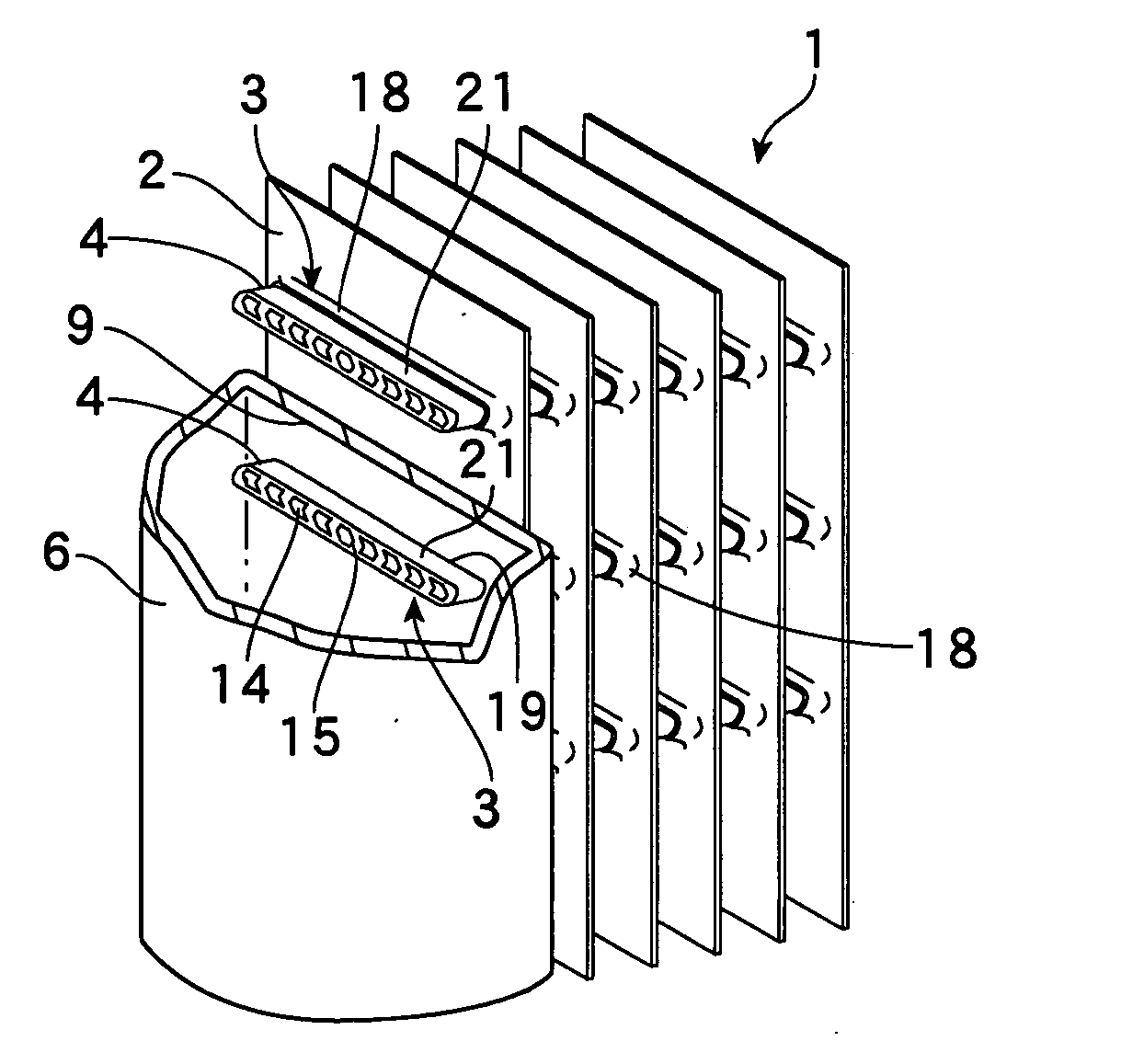
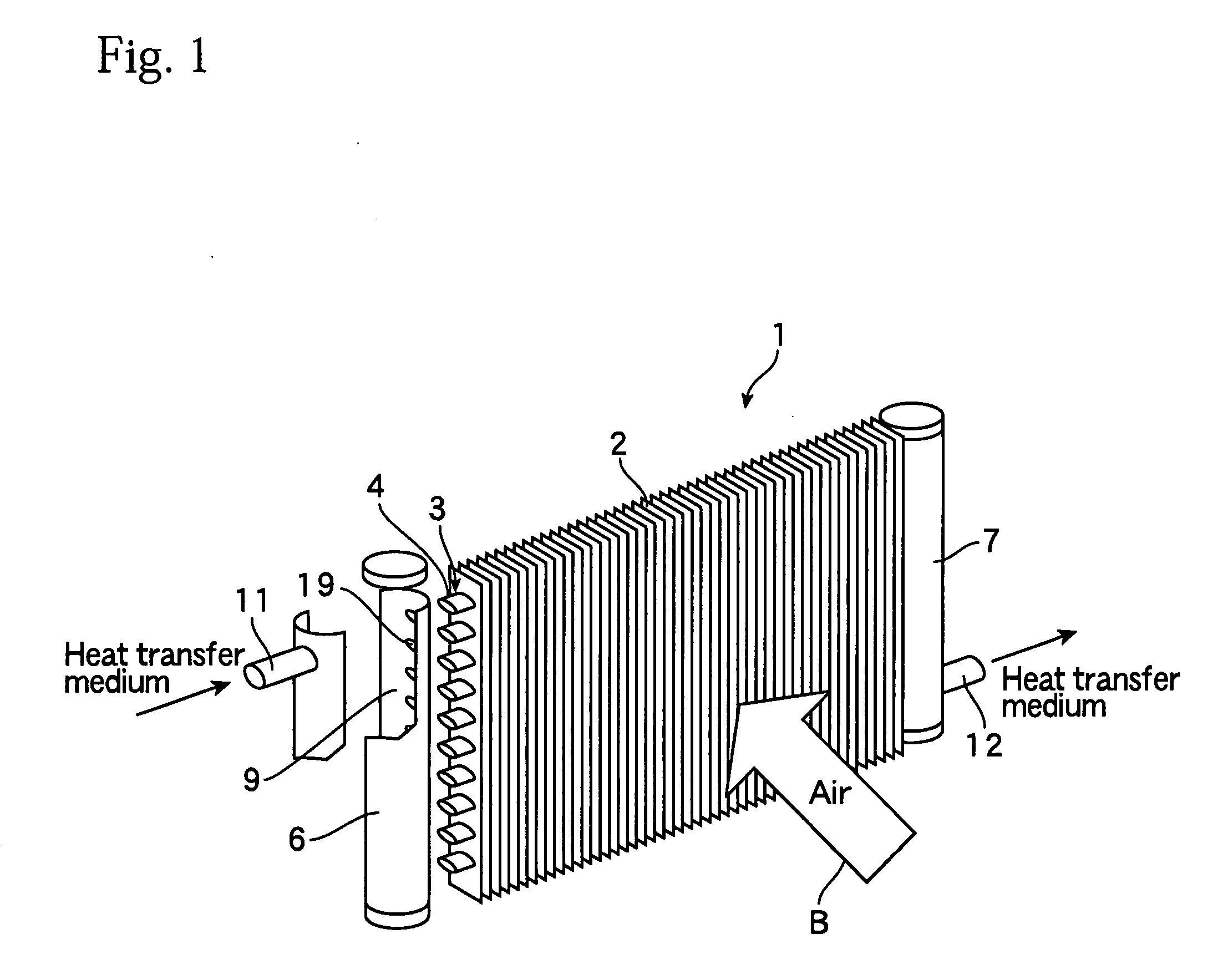
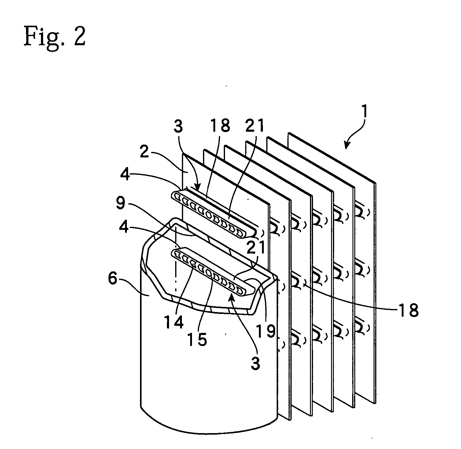
[0025]FIG. 1 schematically shows a heat exchanger that uses multi-channeled flat tubes. FIG. 2 is a perspective view showing an enlargement of a state where the multi-channeled flat tubes have been expanded. The heat exchanger 1 is a plate fin-type heat exchanger. The heat exchanger 1 has a plurality of plate-like fins 2 disposed in parallel at regular intervals and a plurality of multi-channeled flat tubes 3 that are disposed in parallel and are joined to the fins 2 in a state where the multi-channeled flat tubes 3 pass through the fins 2. Each multi-channeled flat tube (flat multi-channeled tube, multi-channel flat tube) 3 is constructed so that the inside of a flat outer tube 21 is divided into a plurality of parallel channels 14 by a plurality of partitions 15. End parts 4 at both ends of the multi-channeled flat tubes 3 are connected to joining holes 19 formed in side walls 9 of headers 6 and 7 positioned on the left and right sides of the heat exchanger 1. A heat transfer medi...


PUM


Abstract

There is provided a multi-channeled flat tube that includes a flat outer tube and a plurality of partitions that divide the inside of the outer tube into a plurality of channels. Each partition in the multi-channeled flat tube has a mountain-shaped cross-sectional form composed of two sides, each of the two sides has a thickness ti and a length a, the partitions are disposed so that a face-to-face distance between adjacent partitions along inner surfaces of the outer tube is Li, and a thickness to of the outer tube satisfies a condition below. By selecting an appropriate pressure when expanding the multi-channeled flat tube, it is possible to prevent deformation of the tube outer surface into a wavy or undulating pattern Li·ti·a2-ti23ato.

Description

TECHNICAL FIELD [0001] The present invention relates to the construction of a multi-channeled flat tube used in a heat exchanger. BACKGROUND ART [0002] A plate-fin heat exchanger equipped with a plurality of plate fins disposed in parallel at regular intervals and a plurality of tubes disposed so as to pass through such fins is known as one example of a heat exchanger used in refrigeration apparatuses, radiators, and the like. One method of manufacturing a plate-fin heat exchanger includes passing the tubes through the fins to assemble, and expanding or enlarging the tubes to join the tubes and fins together. In the expanding the tubes, a rigid rod or a tube expander is inserted into the tubes to press out and widen the tubes from the inside. By expanding the tubes, the tubes and fins are brought into contact. [0003] The use of multi-channeled flat tubes (multi-channel flat tubes) in heat exchangers is also known. A multi-channeled flat tube includes a plurality of partitions provid...

Claims


Application Information

Patent Timeline
Patent Type & Authority Applications(United States)
IPC IPC(8): F28D1/04F28F13/00
CPCF28D1/05366F28F1/32F28F1/022
Inventor MAEZAWA, TAKAHIDEKAWATSU, YASUHIRO
Owner GLOSTER
Why Eureka
Try Eureka