Humidification device and air purifier with humidification function

A humidification device and air technology, applied in the air humidification system, air quality improvement, heating method, etc., can solve the problems of increasing the size of the gasification filter, not suitable, and low moisture gasification efficiency, so as to reduce pressure loss and increase Large surface area, effect of reducing pressure loss

Active Publication Date: 2010-03-24
PANASONIC CORP
View PDF6 Cites 13 Cited by
  • Summary
  • Abstract
  • Description
  • Claims
  • Application Information

AI Technical Summary

Problems solved by technology

Therefore, when performing humidification, since the contact area between the air and the adsorption element is small, the vaporization efficiency of moisture is low. In order to obtain high humidification performance, it is necessar

Method used


Image

  • Humidification device and air purifier with humidification function
  • Humidification device and air purifier with humidification function
  • Humidification device and air purifier with humidification function

Examples


Example

[0085] (first embodiment)

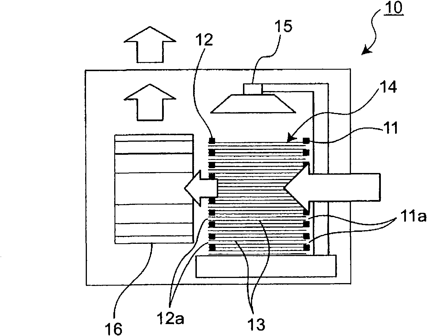
[0086] exist figure 1 A schematic cross-sectional view of the humidifier 10 according to the first embodiment of the present invention is shown in . like figure 1 As shown, the humidifier 10 includes: a gasification filter 14; a sprinkler nozzle 15 as an example of a water supply device that supplies water to the gasification filter 14 to make it wet; The fan 16 is an example of a blower that vaporizes moisture and sends humidified air to the room.

[0087] The gasification filter 14 uses a three-dimensional structure as a filter substrate by connecting a first substrate 11 having a plurality of openings 11a and a second substrate 12 having a plurality of openings 12a with mutual openings 11a. , 12a are connected by connecting multiple connecting fibers 13 to form.

[0088] The water spray nozzle 15 is arranged on the upper portion of the gasification filter 14 , and sprays and supplies water supplied through a pipe or the like to the upper po...

Example

[0098] (second embodiment)

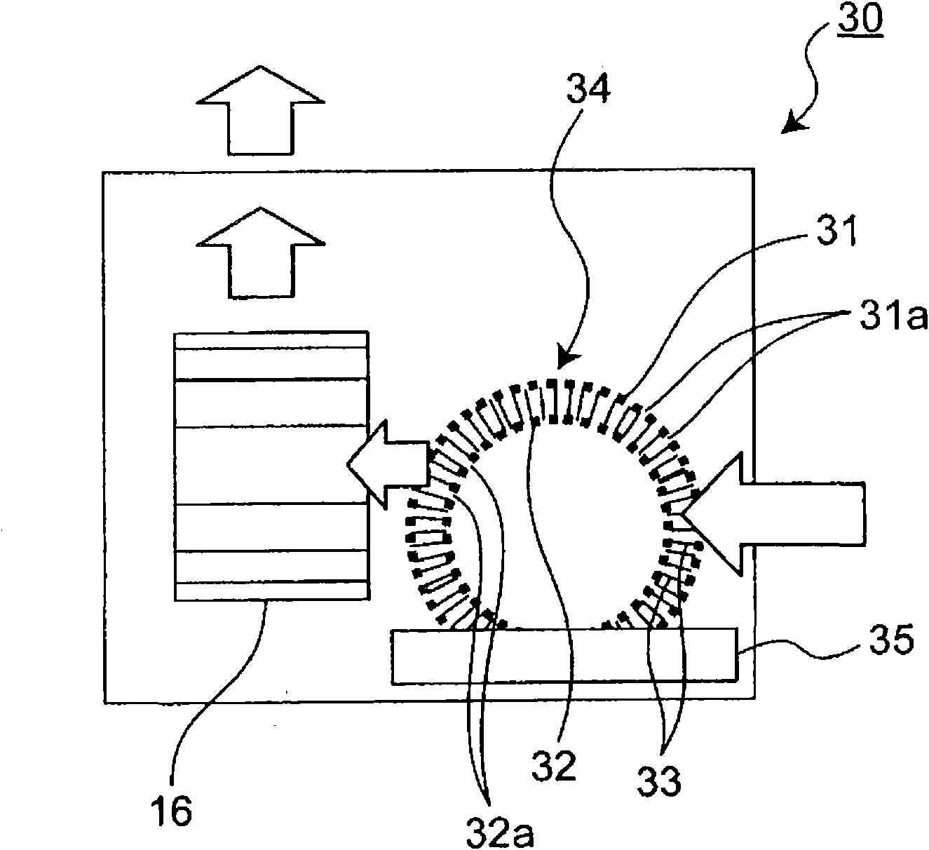
[0099] Next, in image 3 A schematic cross-sectional view of a humidifier 30 according to a second embodiment of the present invention is shown in . like image 3 As shown, the vaporization filter 34 included in the humidifier 30 of the second embodiment has a hollow cylindrical shape. Specifically, the filter base material is formed in a cylindrical shape so that the first base material 31 is located on the outer peripheral surface of the cylinder and the second base material 32 is located on the inner peripheral surface of the cylinder. That is, the first base material 31 is connected by a plurality of connecting fibers 33 so that the opening 31a of the first base material 31 communicates with the opening 32a of the second base material 32 to form an air passage connecting the outer peripheral surface and the inner peripheral surface of the cylinder. with the second substrate 32 . And, if image 3 As shown, a water tank 35 is provided as an ...

Example

[0103] (third embodiment)

[0104] Next, in Figure 4 A schematic perspective view showing an example of the structure of the vaporization filter 44 included in the humidifier according to the third embodiment of the present invention is shown in . like Figure 4 As shown in one example, the three-dimensional structure 45 as the filter base material of the gasification filter 44 has the following structure, that is, the first base material 41 having a plurality of openings 41a and the first base material 41 having a plurality of openings 41a are connected by a plurality of connecting fibers 43. The second base material 42 with an opening 42a, and the opening 41a communicates with the opening 42a to form an air passage. Furthermore, each opening 41a, 42a of the first base material 41 and the second base material 42 has, for example, a hexagonal shape. In the three-dimensional structure 45, the longest diagonal line A of the openings 41a and 42a is 2 mm, the thickness B is 5 ...


PUM

PropertyMeasurementUnit
Diameteraaaaaaaaaa
Thicknessaaaaaaaaaa
Thicknessaaaaaaaaaa

Abstract

A humidification device has an evaporation filter, a water supply device, and a fan device. The evaporation filter uses as a filter base material a three-dimensional structure formed by interconnecting, by connection fibers, a first base material having openings and a second base material having openings, and the first and second base materials are interconnected such that the openings of both the base materials communicate with each other. The water supply device supplies water to the evaporation filter to wet the filter base material. The fan device sends air to the wet filter base material, allows the air to pass through the communicated openings, and sends humidified air out of the evaporation filter. A decrease in humidification ability of the humidification device is suppressed evenif scale is deposited on the evaporation filter. Further, contact efficiency between passing air and water present on the evaporation filter is enhanced, and as a result, although compact in size, the humidification device has high humidification performance.

Description

technical field [0001] The invention relates to a humidifying device for humidifying dried indoor air and an air purifier with humidifying function. Background technique [0002] In the past, in this kind of humidifier, use the device that has following structure, promptly, with respect to the filter (vaporization filter) that becomes wet state, send air by blowing device and make it contact with filter base material, by This vaporizes moisture to obtain humidified air. [0003] An example of an existing humidification device such as Figure 11 shown. exist Figure 11 In the humidifier 100 of , the water-absorptive vaporization filter 101 is arranged such that a part of its lower part is immersed in water 103 in a water tank 102 , and a heater 104 is arranged in front of the vaporization filter 101 . Humidified air is obtained by passing the air heated by the heater 104 through the vaporization filter 101 that sucks up the water 103 from the water tank 102 (for example, re...

Claims


Application Information

Patent Timeline
IPC IPC(8): F24F6/04F24F6/00F24F6/06F24F8/125
CPCF24F2003/1617F24F6/043Y02A50/20F24F8/117F24F8/125
Inventor 织部美绪稻垣纯小田一平
Owner PANASONIC CORP
Why Eureka
Try Eureka