Method for jointing alloy structure part and stainless steel structural part and method for mfg. cutting tool

A joining method and technology of cutting tools, which are applied in the fields of joining alloy components and stainless steel components and manufacturing cutting tools, can solve problems such as increased costs, and achieve the effects of low joint strength and excellent practicability

Inactive Publication Date: 2006-01-18
UNION TOOL
View PDF1 Cites 0 Cited by
  • Summary
  • Abstract
  • Description
  • Claims
  • Application Information

AI Technical Summary

Problems solved by technology

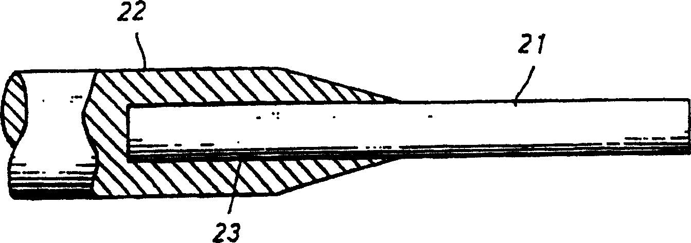
[0009] Conventional Example 2 can reduce the cost compared with Conventional Example 1, but for the part inserted into the recess 23 and the stainless steel for inserting the cemented carbide rod 21, it is necessary to perform extremely high-precision hole processing, and the cemented carbide rod 21 must leave more length for inserting into the concave portion 23, resulting in increased cost

Method used


Image

  • Method for jointing alloy structure part and stainless steel structural part and method for mfg. cutting tool
  • Method for jointing alloy structure part and stainless steel structural part and method for mfg. cutting tool
  • Method for jointing alloy structure part and stainless steel structural part and method for mfg. cutting tool

Examples


Embodiment Construction

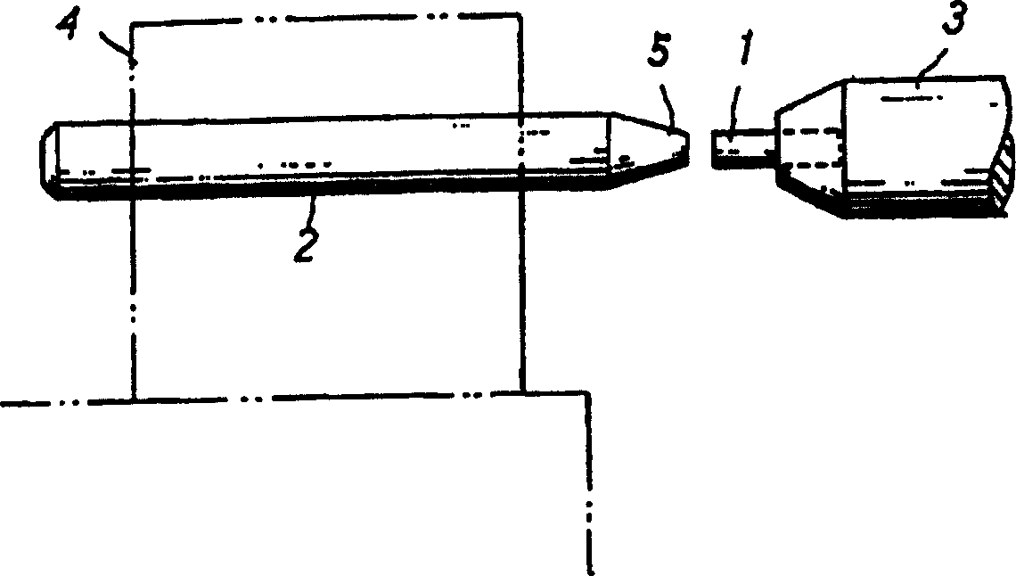
[0025] figure 2 and 3 is a schematic diagram of an embodiment of the present invention, the following reference figure 2 and 3 Examples will be described.

[0026] This embodiment is an example of manufacturing a drill for processing printed circuit boards. Connect the cemented carbide component 1 and the stainless steel component 2 with tungsten carbide as the main component to the electrodes 3 and 4 respectively. The cemented carbide member 1 and the stainless steel member 2 are flowed to join them by welding. Then, a blade portion is processed on the cemented carbide member 1 , and a shank portion is processed on the stainless steel member 2 .

[0027] As the cemented carbide member 1 , a commercially available cemented carbide round rod mainly composed of tungsten carbide is used, and one end surface of the rod is set as a joint surface.

[0028] For the stainless steel member 2, a round bar-shaped rod made of martensitic stainless steel such as SUS440C, SUS420F, S...


PUM


Abstract

A technique for joining the ultrahigh-hardness alloy member whose main component is tungsten carbide with the stainless steel member includes such steps as connecting two electrodes respectively to both members, pressing them together tightly, and flowing pulse current through them via electrodes to weld them together. Its advantages are low cost and high joining strength.

Description

technical field [0001] The present invention relates to a joining method of a superhard alloy member and a stainless steel member and a method of manufacturing a cutting tool using the superhard alloy. Background technique [0002] Tungsten carbide is the main component of cemented carbide mixed with cobalt, tantalum, chromium, etc. It has very high hardness, and is usually used as a raw material for high-precision processing of metal materials and hard materials such as printed circuit boards. [0003] This cemented carbide drill has the following structure. [0004] Conventional example 1 (integral type) [0005] One end of the cemented carbide rod is machined into the blade, and the other end is machined into the shank. [0006] In the previous example 1, because the blade and the handle are integrated, and the whole is made of expensive superhard alloy, there is a disadvantage of extremely high cost. In addition, when the diameter of the blade portion is smaller than ...

Claims


Application Information

Patent Timeline
Patent Type & Authority Patents(China)
IPC IPC(8): B23K11/16B23K11/02B23P15/28
Inventor 片山一郎涌井秀夫
Owner UNION TOOL
Why Eureka
Try Eureka