Thermally insulating housing for cooling device

A refrigeration device and shell technology, which is applied to household refrigeration devices, lighting and heating equipment, household appliances, etc., can solve problems such as unfavorable formation of shrinkage holes, uneven filling of thermal insulation materials, and reduced thermal insulation capacity of shells.

Inactive Publication Date: 2006-03-01
BOSCH SIEMENS HAUSGERATE GMBH
View PDF0 Cites 0 Cited by
  • Summary
  • Abstract
  • Description
  • Claims
  • Application Information

AI Technical Summary

Problems solved by technology

However, for a fast process, which is advantageous for this processing technology itself, the shell skeleton, which consists of the outer cover and the chip-free molded plastic inner lining delimiting the cold room, is in the so-called "grooved state", that is to say , the rear wall of the shell skeleton is placed on a foam mould, it turns out that, especially in the case of large-volume shells, the part close to the machine chamber is unevenly filled with thermal insulation
Thus, the formation of shrinkage cavities that lead to a reduction in the thermal insulation capacity of the housing inevitably occurs in the heat insulating material
The formation of such shrinkage cavities is particularly disadvantageous if at least a part of the insulating housing is designed as a freezer compartment

Method used


Image

  • Thermally insulating housing for cooling device
  • Thermally insulating housing for cooling device
  • Thermally insulating housing for cooling device

Examples


Embodiment Construction

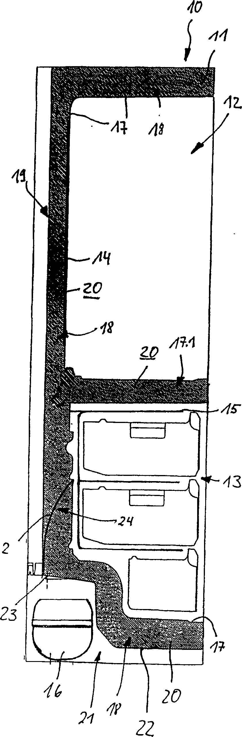
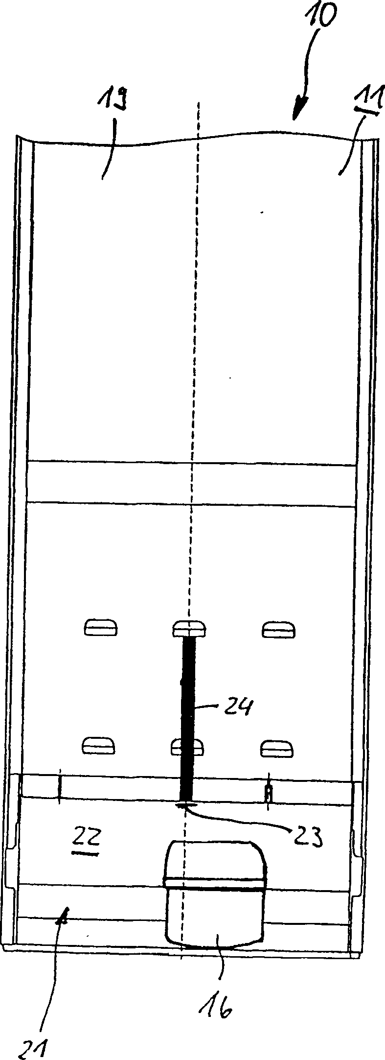
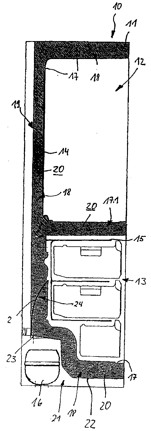
[0022] figure 1 The shown combined cooling-freezing unit 10 has a thermally insulated housing 11 in which a refrigerator compartment 12 and a freezer compartment 13 are arranged below the refrigerator compartment. Whether it is the refrigerator compartment 12 or the freezer compartment 13, they are respectively cooled by an evaporator, wherein the evaporator for cooling the refrigerator compartment 12 is in the form of a so-called cold wall plate evaporator 14; The evaporator is a coiled tube evaporator 15 with a plurality of evaporator planes, and like the cold wall plate evaporator 1, a refrigerant compressor 16 is used to input fluid refrigerant. To cover the refrigerating compartment 12 and the freezing compartment 13, an inner lining 17 formed by chip-free molding of a plastic sheet and serving as an inner cladding is provided, which in this example covers the two refrigerating compartments 12, 12, 13. Between the inner linings for the refrigerating chamber 12 or the fr...


PUM


Abstract

The invention relates to a thermally isolating housing (11) for a cooling device (10) comprising an internal and external surface layer (17, 19) in addition to a thermally insulating layer (20) inserted between entrances of the surface layers (17, 19) in the form of fluidic components, introduced through at least one entrance opening (23) arranged close to a machine chamber (21) for receiving a condensed refrigerating medium (16). A problem of the known cooling device is that the thermally insulating material (20) which turns into mousse is introduced by the high processing pressure thereof, preferably in the upper part of the thermally insulating housing (11). A shrinkage formation therefrom can not be prevented in the deep lying sections of the housing. According to the invention, at least in the neighbouring area of the entrance opening (23) a flat profile (24) is provided for using as a brake for the mousse.

Description

technical field [0001] The present invention relates to a thermally insulated housing for a refrigeration unit, which has an inner and an outer coating and a thermal insulation layer arranged between the two coatings in the form of a fluid initial composition, which can be passed through At least one inlet is inserted between the two claddings, the inlet being arranged here in the vicinity of a machine chamber for accommodating a refrigerant compressor. Background technique [0002] The state of the art of refrigeration units is that the insulating material for thermal insulation is inserted between the inner and outer cladding in the form of a fluid initial composition. Especially for large-volume refrigerating devices such as vertical refrigerating devices and vertical freezing devices and refrigerating combination devices, the fluid insulation material is loaded through an inlet, which is often opened in a so-called bottom tank, The bottom trough covers a machine chamber...

Claims


Application Information

Patent Timeline
Patent Type & Authority Patents(China)
IPC IPC(8): F25D23/06B29C44/38B29C45/00
CPCF25D23/064B29C44/383
Inventor J·瑟尔
Owner BOSCH SIEMENS HAUSGERATE GMBH
Why Eureka
Try Eureka