
Dust collector

A technology of dust collection device and dust collection chamber, which is applied in the direction of exhaust diffusion device, vacuum cleaner, suction nozzle, etc. Effect

Inactive Publication Date: 2006-03-15
SANYO ELECTRIC CO LTD
View PDF0 Cites 0 Cited by
  • Summary
  • Abstract
  • Description
  • Claims
  • Application Information

AI Technical Summary

Problems solved by technology

[0004] But, in above-mentioned dust collecting device (10), as Figure 10 As shown, due to the rotation of the rotating brush (2) in the dust collection chamber (36) there will be a vortex as shown by the arrow, so, from the dust suction port (3) through the air flow through the port (34) into the dust collection chamber The flow rate of the airflow in the chamber (36) is reduced, and there is a problem of low dust collection efficiency
[0005] In addition, as the rotating brush (2) rotates counterclockwise as indicated by the arrow, the air is drawn into the brush cover wall (93) and the rotating brush (2) to the brush portion (21) as indicated by the arrow. In the gap W between the outer peripheral ends, the air that is involved becomes the airflow that is blown from the dust suction port (3) to the front of the dust collector, and there is a tendency to push the dust (53) on the ground (5) to the direction indicated by the arrow. The direction shown blows away the problem
In addition, the dust swept up by the rotating brush (2) is involved in the aforementioned gap W and cannot be trapped in the dust collection chamber (36).
[0006] Furthermore, the airflow flowing in from the dust suction port (3) collides with the end (93a) of the brush cover wall (93), as shown by the arrow, turbulent flow occurs in the airflow, and the airflow flow rate flowing into the dust collecting chamber (36) decreases , there is a problem of low dust collection efficiency

Method used


Image

  • Dust collector
  • Dust collector
  • Dust collector

Examples


Embodiment Construction

[0023] A plurality of embodiments of the present invention will be specifically described below with reference to the drawings.

[0024] first embodiment

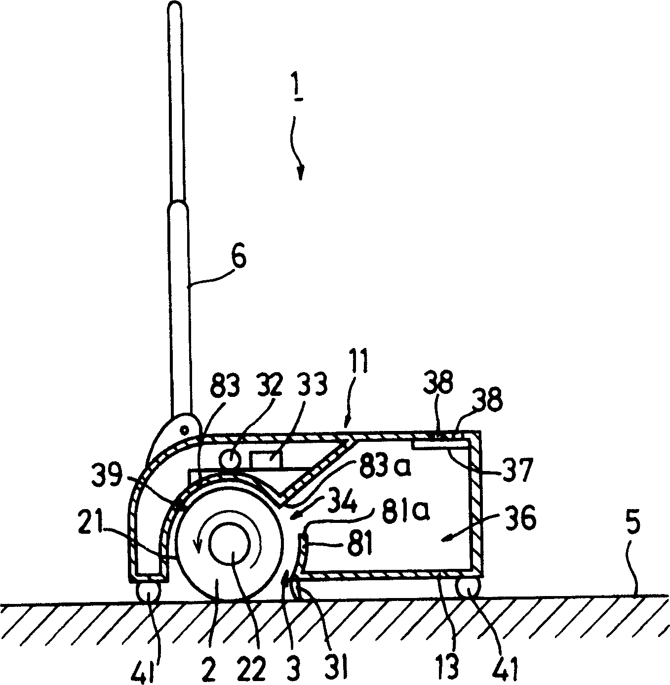
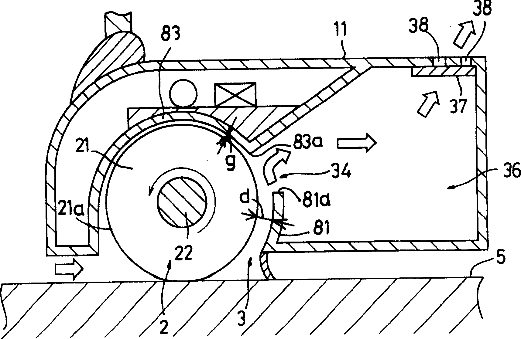
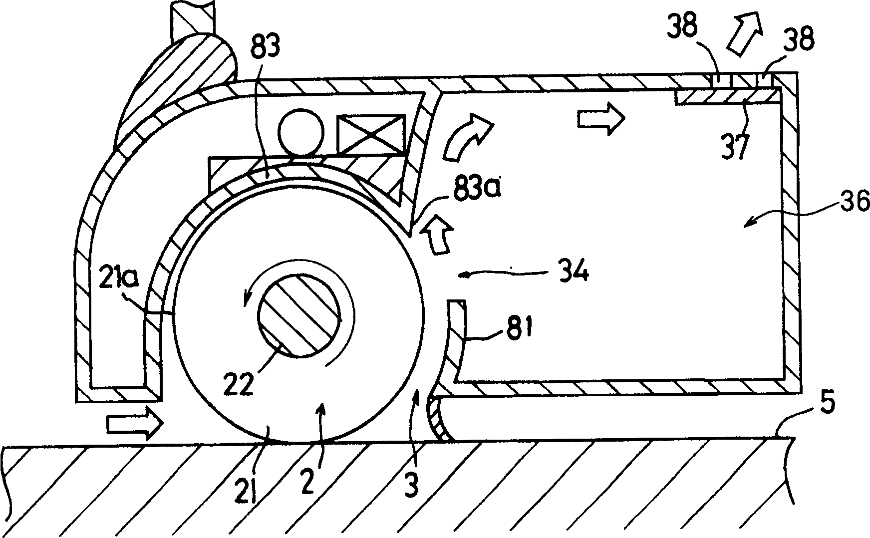
[0025] Such as figure 1 As shown, the dust collecting device of this embodiment has a housing (11) and a rotating brush (2) accommodated in the housing (11), and an operating handle (6) is installed on the upper surface of the housing (11). In the inside of the casing (11), a rotating brush housing chamber (39) for accommodating the rotating brush (2), a dust collection chamber (36) for accumulating dust, and accommodating and generating power for rotating the rotating brush (2) are formed. A motor (32), and a secondary battery (33) that supplies electric energy to the motor (32). The rotating brush (2) has a rotating shaft (22) and a brush portion (21) formed on the outer peripheral surface of the rotating shaft (22), and one end of the rotating shaft (22) is connected to the motor (32) to the motor (32) via a belt in...


PUM


Abstract

A dust collecting device has a suction port in a bottom of frame member, a dust collecting chamber and a rotating brush chamber 39 disposed in the frame member, the rotating brush chamber being communicating with the dust collecting chamber through an air passage port. A rotating brush driven by a motor to rotate is provided in the rotating brush chamber. The dust on floor can be swept up by the rotation of the rotating brush and collected in the dust collecting chamber through the air passage port. The frame member is provided with a brush cover wall covering the rotating brush from top and facing the rotating brush chamber, and an air stream guide wall between the rotating brush chamber and the dust collecting chamber, and a stop wall extending from an upper end of the air stream guide wall in the interior of the dust collecting chamber.

Description

technical field [0001] The invention relates to a dust collection device with a rotating brush. Background technique [0002] As such a dust collection device, the applicant is applying to the Japan Patent Office Figure 9 The dust collection device (10) shown. The dust collection device (10) comprises a housing (12), a rotating brush (2) equipped in the housing (12), and a dust collection chamber (36) formed in the housing (12). 12) A motor (32) for rotationally driving the rotating brush (2) and a secondary battery (33) for supplying power to the motor (32) are installed. On the bottom wall (14) of housing (12), offer dust suction port (3), in the inside of housing (12), form the rotary brush housing chamber (39) with dust suction port (3) as opening, in the A dust collecting member (31) pointing to the ground (5) is protrudingly arranged on the edge of the opening of the dust suction port (3) behind the rotating brush (2). The four corners of the bottom wall (14) of th...

Claims


Application Information

Patent Timeline
Patent Type & Authority Patents(China)
IPC IPC(8): A47L5/30A47L9/04A47L11/24A47L5/24
CPCA47L5/30A47L9/0081A47L9/0411A47L9/0477
Inventor 水间圣人广濑达也
Owner SANYO ELECTRIC CO LTD
Learn More